Faber Levante E Скачать руководство пользователя страница 21

21

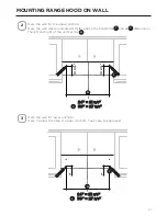
Mark the wall for the upper anchors.  

0DUNWKHZDOOZKHUHLQGLFDWHGDERYHWKHKRUL]RQWDO

I

 line at 

J

 distance on 

the left and right of the vertical line 

H

 .

3

1”

1”

24” - - > A= 21

3/8

A

15/16

15/16

A

Mark the wall for lower anchors.
Mark 1” below the Step 2. Upper Anchors. Take care to keep level.

24" = 21 

24" = 21 

3/8

3/8

"

30" = 27 

30" = 27 

3/8

3/8

"

24" = 21 

24" = 21 

3/8

3/8

"

30" = 27 

30" = 27 

3/8

3/8

"

MOUNTING RANGE HOOD ON WALL

2

I

J

H

I

J

H

Содержание Levante E

Страница 1: ...00 LEVE30SS200 LEVE24WH200 LEVE30WH200 Installation Instructions Use and Care Information Instructions d installation Utilisez et d entretien Instrucciones de instalaci n Informaci n de uso y cuidado...

Страница 2: ...All ducted venting method All ducted venting method 12 Ducted venting method options 13 Ducted 7 round outlet 14 Ducted 3 1 4 x 10 Rectangular Outlet on top 16 Ducted 3 1 4 x 10 Rectangular Outlet rea...

Страница 3: ...QJ FDOOHG RX FDQ JKW WKH UH ZLWK RXU EDFN WR DQ H LW Based on Kitchen Firesafety Tips published by NFPA WARNING TOREDUCETHERISKOFFIREORELECTRICSHOCK donotusethisfanwith any solid state speed control d...

Страница 4: ...extend either through the wall or the roof The length of the ductwork and the number of elbows should be kept to a minimum to SURYLGH HI FLHQW SHUIRUPDQFH 7KH VL H RI WKH GXFWZRUN VKRXOG EH XQLIRUP R...

Страница 5: ...Thisapplianceshouldbeconnecteddirectlytothefuseddisconnect orcircuitbreaker WKURXJK H LEOH DUPRUHG RU QRQPHWDOOLF VKHDWKHG FRSSHU FDEOH OORZ VRPH VODFN LQ the cable so the appliance can be moved if se...

Страница 6: ...6 RANGE HOOD DIMENSIONS 7 1 4 3 23 15 16 29 15 16 35 15 16...

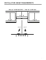
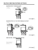
Страница 7: ...7 MIN 24 OVER ELECTRIC MIN 30 OVER GAS Min 24 Min 30 INSTALLATION HEIGHT REQUIREMENTS...

Страница 8: ...8 PARTS REF PART A Hood body Includes Controls Light Filters Blower 1 B Damper 1 C 7 Round Flange 1 X KDUFRDO OWHU 1 Y UHDVH OWHU 1 REF PART E 3R L 6FUHZV 4 F 7RU 6FUHZV 4 PARTS INCLUDED B C A X Y...

Страница 9: ...per Wire connectors Power Supply Cable Drywall plugs or other suitable wall fasteners based on your installation DOO DS 5RRI DS 1HHGV WR EH SXUFKDVHG VHSDUDWHO TOOLS NEEDED TOOL Tape Measure Pencil OH...

Страница 10: ...13 16 13 16 CHOOSE VERTICAL OR HORIZONTAL ELECTRICAL CONNECTION KNOCKOUT S PREPARE FOR ELECTRICAL REMOVE HOOD JUNCTION BOX Remove the hood junction box from inside the hood Set the cover and its moun...

Страница 11: ...with a screwdriver or other tool During the installation thread Power Supply Cable through this hole 2 7RS ROH 9HUWLFDO Choose the top hole for the electric connection and break with a screwdriver or...

Страница 12: ...TIONS ONLY Remove the baffle from the top of the hood Reinstall the baffle so the short side marked VENTED is visible The long side of the baffle should be inside the hood 1 9 17 LV YLVLEOH 2 QVWDOO W...

Страница 13: ...OUTLET Vertical Horizontal DUCTED WITH 3 1 4 X 10 RECTANGULAR OUTLET Vertical Horizontal 7 Rear Top 10 3 1 4 10 3 1 4 Rear Top Go to page 14 Go to page 16 NON DUCTED RECIRCULATION OPTION Requires pur...

Страница 14: ...ere indicated Remove both the rectangular and semicircle areas with metal shears Rear Top 7 Required 7 Round Damper purchase separately 1 Caution If an elbow is required do it as far away from the hoo...

Страница 15: ...he Roof or Wall Cap purchased separately and then attach ductwork Go to page 19 2 Install 7 Round Damper purchased separately Secure damper with foil duct tape 3 NOTE The Flange must be mounted with t...

Страница 16: ...luded rectangular air outlet with two screws F Connect the metal ductwork to the Roof or Wall Cap purchased separately and then attach ductwork Rear Top Top 3 1 4 x 10 DUCTED 3 1 4 X 10 RECTANGULAR OU...

Страница 17: ...ectangular air outlet with two screws F 1 2 Torx Screwdriver F 7RU 6FUHZV DUCTED 3 1 4 X 10 RECTANGULAR OUTLET REAR Caution If an elbow is required do it as far away from the hood s exhaust opening as...

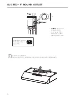
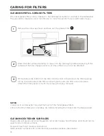
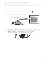
Страница 18: ...18 NON DUCTED RECIRCULATION OPTION Go to page 19 1 QVWDOO WKH FKDUFRDO OWHU X and attach the screw as shown X...

Страница 19: ...19 CHOOSING THE MOUNTING METHOD Installation for Mounting on the Wall Installation for Mounting to the cabinet Page 20 Page 24...

Страница 20: ...t the center of the area in which the hood will be installed Draw a horizontal line I from where the bottom edge of hood will be located to a minimum of 24 above an electric cooking surface and 30 abo...

Страница 21: ...tance on the left and right of the vertical line H 3 1 1 24 A 21 3 8 A 4 15 16 4 15 16 A Mark the wall for lower anchors Mark 1 below the Step 2 Upper Anchors Take care to keep level 24 21 24 21 3 8 3...

Страница 22: ...HU SRLQWV PDUNHG LQ VWHS Iffastenerlocationsdonotalignwiththestuds insertthepurchasedwallplugsintheholes In upper holes use two of the supplied screws E to secure the hood body to the wall 5 Pozi Scre...

Страница 23: ...23 Using two remaining screws E anchor the hood in lower holes as indicated 6 MOUNTING RANGE HOOD ON WALL Pozi Screwdriver E 3R L 6FUHZV...

Страница 24: ...le on the Range Hood for the power cord See Section CHOOSE VERTICAL OR HORIZONTAL ELECTRICAL CONNECTION KNOCKOUT S and pass the cord through the appropriate hole Lift the hood to the cabinet and pass...

Страница 25: ...or wood shims 3 Attach the Hood body with 4 screws E from the bottom available with the hood 4 E 3R L 6FUHZV Pozi Screwdriver MOUNTING RANGE HOOD UNDER THE CABINET Cabinet X 24 30 RRG VKLPV UHFHVVHG...

Страница 26: ...Connections Attach the White lead of the Power Supply A to the White lead of the Range Hood D with a twist on type connector Attach the Black lead of the Power Supply to the Black lead of the Range H...

Страница 27: ...DLQWHG 6XUIDFHV RQ VRPH PRGHOV Do not use a steel wool pads or other abrasive cleaners they will scratch the surface Clean grease laden surfaces of the hood frequently To clean the hood surface use a...

Страница 28: ...PRYHG 1 2 3 CLEANING METAL GREASE FILTERS 7KH PHWDO JUHDVH OWHUV FDQ EH FOHDQHG LQ KRW GHWHUJHQW VROXWLRQ RU ZDVKHG LQ WKH GLVKZDVKHU They should be cleaned every 2 months use or more frequently if us...

Страница 29: ...ct Faber for more information on the replacement charcoal DO NOT rinse or put charcoal OWHUV LQ DQ DXWRPDWLF GLVKZDVKHU 5HSODFHDEOH FKDUFRDO ILOWHU X Pull down on the center of the front edge of the f...

Страница 30: ...terclockwise to unlock light and pull out Replace with new light of same type standard incandescent making sure socket is properly inserted into the housing of the lamp holder Attention The bulbs coul...

Страница 31: ...31 WIRING DIAGRAM E D 9 7 02725 5 1 2 7 5 E 5 2 D 1 7 22 17 51 21752 03 7 1 1 9DF...

Страница 32: ...ng from accident alteration misuse abuse fire flood acts of God improper installation installation not in accordance with electrical or plumbing codes or Faber documentation or use of products not app...

Страница 33: ...e verticale ou horizontale 42 Options avec ventilation canalis e 45 Canalisation conduit circulaire 7 46 Canalisation conduit rectangulaire 3 1 4 x 10 du dessus 48 Canalisation conduit rectangulaire 3...

Страница 34: ...mouill pour teindre le feu Cela pourrait provoquer une violente explosion de vapeur d Utilisez un extincteur UNIQUEMENT si 9RXV rWHV FHUWDLQ TX LO V DJLW G XQ H WLQFWHXU GH FODVVH HW TXH YRXV FRQQDLVV...

Страница 35: ...ieur ou le plancher autour du clapet O Q HVW SDV UHFRPPDQGp G XWLOLVHU GHV FRQGXLWV H LEOHV HV FRQGXLWV H LEOHV SURYRTXHQW XQH FRQWUH SUHVVLRQ HW GH OD WXUEXOHQFH TXL GLPLQXHQW JUDQGHPHQW O HI FDFLWp...

Страница 36: ...e jeu dans le c ble pour permettre le d placement de l appareil si des travaux G HQWUHWLHQ V DYpUDLHQW QpFHVVDLUHV 8Q UDFFRUG GH FRQGXLW KRPRORJXp SDU O 8 GH doit tre install aux deux extr mit s du c...

Страница 37: ...ILISEZ PAS une conduite de gaz pour la mise la terre N INSTALLEZ PAS un fusible sur le circuit neutre ou le circuit de mise la terre La pr sence d un fusible dans le circuit neutre ou de mise la terre...

Страница 38: ...38 DIMENSIONS DE LA HOTTE 7 1 4 3 23 15 16 29 15 16 35 15 16...

Страница 39: ...39 Min 24 Min 30 HAUTEUR REQUISE POUR L INSTALLATION MIN 24 AU DESSUS D UNE SURFACE LECTRIQUE MIN 30 AU DESSUS D UNE SURFACE AU GAZ...

Страница 40: ...kWL GH OD KRWWH LQFOXDQW FRPPDQGHV pFODLUDJH OWUHV YHQWLODWHXU 1 B Registre 1 C Bride circulaire 7 1 X Filtre charbon 1 Y Filtre graisse 1 R F PI CE E 9LV j WrWH 3R LGULY 4 F 9LV j WrWH pWRLOH 4 PI C...

Страница 41: ...V C ble d alimentation lectrique Chevilles pour cloison s che ou autre syst me de DWLRQ PXUDO HQ IRQFWLRQ GH YRWUH LQVWDOODWLRQ ODSHW GH WRLWXUH FODSHW PXUDO RLW rWUH DFKHWp s par ment OUTILS REQUIS O...

Страница 42: ...1 RRG XQFWLRQ R Pr paration de la hotte pour les entr es pr d coup es lectriques PR PARATION DU SYST ME D LECTRICIT RETRAIT DE LA BO TE DE JONCTION DE LA HOTTE Retirez la bo te de jonction de l int ri...

Страница 43: ...un autre outil Pendant l installation faites passer le c ble d alimentation lectrique par ce trou 7URX VXSpULHXU YHUWLFDO Choisissez le trou sup rieur pour le raccordement lectrique et percez le l ai...

Страница 44: ...NSAVECCONDUITSUNIQUEMENT Retirez le d flecteur du haut de la hotte R installez le d flecteur de sorte que le c t court marqu VENTIL soit visible Le c t long du d flecteur doit se trouver l int rieur d...

Страница 45: ...IT AVEC SORTIE RONDE DE 7 Vertical Horizontal CONDUIT AVEC SORTIE RECTANGULAIRE DE 3 1 4 X 10 Vertical Horizontal Arri re Haut Arri re Haut Allez la page 46 Allez la page 48 OPTION DE RECIRCULATION SA...

Страница 46: ...tirez les zones rectangulaires et semi circulaires avec des cisailles m taux Arri re Haut 7 1pFHVVDLUH veuillez acheter le clapet rond de 7 s par ment Attention 6L XQ coude est n cessaire r alisez le...

Страница 47: ...lique ronde de 7 au capuchon de toit ou de paroir achet VpSDUpPHQW SXLV H OD JDLQH Allez la page 51 3 Installez le clapet rond de 7 achet s par ment Fixez le clapet avec du ruban adh sif en toile REMA...

Страница 48: ...e fournie l aide de deux vis F Raccordez le conduit m tallique au clapet de toiture ou au clapet mural achet s par ment puis raccordez les conduits Arri re Haut Haut 1 4 x 10 CANALISATION CONDUIT RECT...

Страница 49: ...laire fournie l aide de deux vis F 1 2 Tournevis toile F 9LV j WrWH pWRLOH CANALISATION CONDUIT RECTANGULAIRE 55 5 Attention 6L YRXV GHYH installer un coude placez le le plus loin possible de l ouvert...

Страница 50: ...50 1 X OPTION DE RECIRCULATION SANS CONDUIT QVWDOOH OH OWUH j FKDUERQ X HW H OD YLV FRPPH LQGLTXp...

Страница 51: ...51 CHOISIR LA M THODE DE MONTAGE Installation pour montage mural Installation pour montage l armoire Page 52 Page 56...

Страница 52: ...a hotte sera install e Tracez une ligne horizontale I l endroit correspondant au bas de la hotte cet emplacement doit se trouver une distance d au moins 24 de la surface de cuisson si elle est lectriq...

Страница 53: ...e J droite et gauche de la ligne verticale H 3 1 1 24 A 21 3 8 A 4 15 16 4 15 16 A Marquez l emplacement des ancrages du bas Tracez un rep re 1 sous les marques de l tape 2 ancrages du haut Assurez vo...

Страница 54: ...H 6L O HPSODFHPHQW GHV DWLRQV Q HVW SDV DOLJQp DYHF OHV FKHYURQV LQVpUH OHV FKHYLOOHV achet es dans les trous Dans les trous du haut utilisez deux des vis fournies E SRXU HU OH EkWL GH OD KRWWH au mur...

Страница 55: ...55 Utilisez les deux vis restantes E dans les trous du bas pour ancrer la hotte au mur 6 MONTAGE DE LA HOTTE AU MUR Tournevis Pozidriv E 9LV j WrWH 3R LGULY...

Страница 56: ...hotte pour le cordon d alimentation voir la section CHOISIR DES CONNEXIONS LECTRIQUES VERTICALES OU HORIZONTALES et faites passer le cordon dans le trou appropri Soulevez la hotte jusqu l armoire et...

Страница 57: ...OH sch ma de la page pr c dente REMARQUE Enfoncez les 4 E vis moiti dans le fond de l armoire ou les cales en bois Fixez le corps de la hotte l aide de 4 vis E par le bas disponibles avec la hotte E...

Страница 58: ...de connexion UDQFKH OH O EODQF GH O DOLPHQWDWLRQ A DX O EODQF GH OD KRWWH D l aide d un connecteur verrouill par rotation UDQFKH OH O QRLU GH O DOLPHQWDWLRQ DX O QRLU GH OD KRWWH B l aide d un connec...

Страница 59: ...XU FHUWDLQV PRGqOHV 1 XWLOLVH SDV GH WDPSRQV HQ ODLQH G DFLHU RX G DXWUHV QHWWR DQWV DEUDVLIV LOV UD HUDLHQW OD surface Nettoyez fr quemment les surfaces de la hotte charg es de graisse Pour nettoyer...

Страница 60: ...JUDLVVH PpWDOOLTXHV SHXYHQW rWUH QHWWR pV GDQV XQH VROXWLRQ GpWHUJHQWH FKDXGH RX lav s au lave vaisselle OV GRLYHQW rWUH QHWWR pV WRXV OHV PRLV G XWLOLVDWLRQ RX SOXV IUpTXHPPHQW VL O XWLOLVDWLRQ HVW p...

Страница 61: ...tactez Faber pour plus d informations sur le charbon de remplacement VITEZ DE rincer RX PHWWUH OHV OWUHV j FKDUERQ GDQV XQ ODYH YDLVVHOOH DXWRPDWLTXH Tirez vers le bas sur le centre du bord avant du f...

Страница 62: ...aire pour la d verrouiller et retirez la Remplacez la par une nouvelle ampoule du m me type incandescente standard en vous assurant que la douille est correctement ins r e dans le logement du porte la...

Страница 63: ...63 SCH MA DE C BLAGE E D 9 7 02725 5 1 2 7 5 E 5 2 D 1 7 22 17 51 21752 03 7 1 1 9DF...

Страница 64: ...ng from accident alteration misuse abuse fire flood acts of God improper installation installation not in accordance with electrical or plumbing codes or Faber documentation or use of products not app...

Страница 65: ...74 Opciones de m todo de ventilaci n canalizada 77 Canalizada salida redonda de 7 78 Canalizada salida rectangular de 3 1 4 x 10 en la parte superior 80 Canalizada salida rectangular de 3 1 4 x 10 en...

Страница 66: ...i 1 Usted sabe que tiene un extintor Clase ABC y ya sabe c mo operarlo 2 El incendio es peque o y est contenido en el rea donde comenz 3 Se llama al departamento de bomberos 4 Puede luchar contra el i...

Страница 67: ...piso alrededor de la tapa 12 VH UHFRPLHQGDQ FRQGXFWRV H LEOHV RV FRQGXFWRV H LEOHV FUHDQ XQD FRQWUDSUHVLyQ y turbulencias de aire que reducen en gran medida el rendimiento Aseg rese de que haya espac...

Страница 68: ...Protection Association Batterymarch Park Quincy Massachusetts 02269 Este electrodom stico debe conectarse directamente a la desconexi n por fusible o GLV XQWRU D WUDYpV GH XQ FDEOH H LEOH EOLQGDGR R Q...

Страница 69: ...i n a tierra NO conecte a tierra a una tuber a de gas NO tenga un fusible en el circuito neutro o de tierra Un fusible en el circuito neutro o de tierra podr a provocar una descarga el ctrica RQVXOWH...

Страница 70: ...70 DIMENSIONES DE LA CAMPANA EXTRACTORA 7 1 4 3 23 15 16 29 15 16 35 15 16...

Страница 71: ...71 Min 24 Min 30 REQUISITOS DE ALTURA DE INSTALACI N M N 24 SOBRE PLACA EL CTRICA MIN 30 SOBRE PLACA DE GAS...

Страница 72: ...A XHUSR GH OD FDPSDQD QFOX H FRQWUROHV OX OWURV YHQWLODGRU 1 B Registro 1 C Brida redonda de 7 1 X Filtro de carb n vegetal 1 Y Filtro de grasa 1 REF PIEZA E 7RUQLOORV 3R L 4 F 7RUQLOORV 7RU 4 PIEZAS...

Страница 73: ...Cable de suministro de energ a Tacos para pared de yeso u otros sujetadores de pared adecuados seg n su instalaci n D WDSD GH OD SDUHG GHO WHFKR GHEHQ FRPSUDUVH SRU separado HERRAMIENTAS NECESARIAS H...

Страница 74: ...ELEGIR EL PANEL EL CTRICO VERTICAL U HORIZONTAL PREPARACI N DE LA INSTALACI N EL CTRICA EXTRACCI N DE LA CAJA DE CONEXIONES DE LA CAMPANA Retirar la caja de conexiones de la campana del interior de la...

Страница 75: ...GHVWRUQLOODGRU u otra herramienta XUDQWH OD LQVWDODFLyQ SDVDU HO FDEOH GH DOLPHQWDFLyQ SRU HVWH RUL FLR 2UL FLR VXSHULRU YHUWLFDO OHJLU HO RUL FLR VXSHULRU SDUD OD FRQH LyQ HOpFWULFD URPSHU FRQ XQ GH...

Страница 76: ...CON CONDUCTOS Retirar el deflector de la parte superior de la campana Vuelva a instalar el deflector de manera que el lado corto marcado como VENTILADO sea visible El lado largo del deflector debe es...

Страница 77: ...CON SALIDA REDONDA DE 7 Vertical Horizontal CONDUCTO CON SALIDA RECTANGULAR DE 3 1 4 X 10 Vertical Horizontal Trasera Superior Trasera Superior Ir a p gina 78 Ir a p gina 80 OPCI N DE RECIRCULACI N S...

Страница 78: ...ndica Retirar las zonas rectangulares y semic rculos con tijeras de metal Trasera Superior Se requiere el regulador redondo de 7 se compra por separado Precauci n Si se requiere un codo h galo lo m s...

Страница 79: ...met lico redondo de 7 a la tapa del techo o de la pared que VH FRPSUD SRU VHSDUDGR OXHJR MDU HO FRQGXFWR Ir a p gina 83 Instalar el regulador redondo de 7 comprado separadamente Asegurar el regulador...

Страница 80: ...ida con dos tornillos F Conecte los conductos met licos al techo o la tapa de pared que se compran por separado y luego conecte los conductos Parte trasera Parte superior Parte superior 3 1 4 x 10 CAN...

Страница 81: ...incluida con dos tornillos F 1 2 Destornillador Torx F 7RUQLOORV 7RU CANALIZADA SALIDA RECTANGULAR DE 3 1 4 X 10 EN LA PARTE TRASERA Precauci n Si se requiere un codo h galo lo m s lejos posible de la...

Страница 82: ...82 1 X OPCI N DE RECIRCULACI N SIN CONDUCTOS QVWDODU HO OWUR GH FDUEyQ YHJHWDO X MH HO WRUQLOOR FRPR VH PXHVWUD...

Страница 83: ...83 ELECCI N DEL M TODO DE MONTAJE Instalaci n para montaje en la pared Instalaci n para montaje en gabinete P gina 84 P gina 88...

Страница 84: ...o de la zona en la que se instalar la campana Trace una l nea horizontal I desde donde se ubicar el borde inferior de la FDPSDQD D XQ PtQLPR GH VREUH XQD VXSHU FLH GH FRFFLyQ HOpFWULFD VREUH XQD VXSHU...

Страница 85: ...a y derecha de la l nea vertical H 3 1 1 24 A 21 3 8 A 4 15 16 4 15 16 A Marque la pared para los anclajes inferiores Marque 1 debajo del Paso 2 Anclajes superiores Tenga cuidado de mantener el nivel...

Страница 86: ...iones de los sujetadores no se alinean con los postes inserte los tacos de pared comprados en los agujeros EQ ORV RUL FLRV VXSHULRUHV XVH GRV GH ORV WRUQLOORV VXPLQLVWUDGRV E para asegurar el cuerpo d...

Страница 87: ...87 Usando dos tornillos restantes E ancle la campana en los agujeros inferiores como se indica 6 MONTAJE DE LA CAMPANA EXTRACTORA EN LA PARED Destornillador Pozi E 7RUQLOORV 3R L...

Страница 88: ...UDFWRUD SDUD HO FDEOH GH DOLPHQWDFLyQ RQVXOWDU la secci n ELEGIR EL PANEL EL CTRICO VERTICAL U HORIZONTAL y pasar el FDEOH SRU HO RUL FLR FRUUHVSRQGLHQWH Levantar la campana hasta el armario y pasar e...

Страница 89: ...HO diagrama de la p gina anterior NOTA Introducir los 4 E parcialmente en el fondo del armario o en las calzas de madera Fijar el cuerpo de la campana con 4 tornillos E desde la parte inferior disponi...

Страница 90: ...l cable blanco de la fuente de alimentaci n A al cable blanco de campana extractora D con un conector de cable tipo twist on Conecte el cable negro de la fuente de alimentaci n al cable negro de la ca...

Страница 91: ...humo y los olores de la cocina 6XSHU FLHV 3LQWDGDV HQ DOJXQRV PRGHORV 1R XWLOL DU HVSRQMDV GH ODQD GH DFHUR X RWURV OLPSLDGRUHV DEUDVLYRV UD DUiQ OD VXSHU FLH LPSLDU FRQ IUHFXHQFLD ODV VXSHU FLHV GH O...

Страница 92: ...GH JUDVD PHWiOLFRV SXHGHQ OLPSLDUVH HQ XQD VROXFLyQ GH GHWHUJHQWH FDOLHQWH R ODYDUVH en el lavavajillas Deben limpiarse cada 2 meses de uso o con mayor frecuencia si el uso es particularmente intenso...

Страница 93: ...n contacto con Faber para obtener m s informaci n sobre el carb n vegetal de UHSXHVWR 12 HQMXDJXH QL SRQJD ORV OWURV GH FDUEyQ YHJHWDO HQ XQ ODYDYDMLOODV DXWRPiWLFR Tire hacia abajo del centro del bor...

Страница 94: ...s del reloj para desbloquearla y s quela Sustituya la l mpara por una nueva del mismo tipo incandescente est ndar asegur ndose de que el enchufe est correctamente insertado en la carcasa del portal mp...

Страница 95: ...95 DIAGRAMA DE CABLEADO E D 9 7 02725 5 1 2 7 5 E 5 2 D 1 7 22 17 51 21752 03 7 1 1 9DF...

Страница 96: ...m stico distinto al normal 4 Da os resultantes de accidente alteraci n mal uso abuso incendio inundaci n eventos naturales instalaci n incorrecta instalaci n no conforme a los c digos el ctricos o de...

Страница 97: ......

Страница 98: ......

Страница 99: ......

Страница 100: ...991 0676 427_02 220405 D000000008483_01...

Отзывы: