Faber FABULA EVO+WH A90 Скачать руководство пользователя страница 36

FR 

3

6

36 

Panneau aspiration périmétrale 

• Ouvrir la porte de la hotte.

(Voir paragraphe Utilisation).

• Retirer les deux bandes de ru-

ban adhésif qui fixent le pan-

neau seulement durant le trans-

port.

Содержание FABULA EVO+WH A90

Страница 1: ...Instructions Manual Manuel d Instructions Bedienungsanleitung Manual de instrucciones...

Страница 2: ...IQUES 25 INSTALLATION 27 UTILISATION 37 NETTOYAGE ET ENTRETIEN 39 INHALTSVERZEICHNIS SICHERHEITSINFORMATIONEN 41 CHARAKTERISTIKEN 44 MONTAGE 46 BEDIENUNG 56 REINIGUNG UND WARTUNG 58 NDICE INFORMACI N...

Страница 3: ...eight please refer to the paragraphs on working dimensions and installation If the instructions for installation for the gas hob specify a greater distance this must be respected Check that the mains...

Страница 4: ...to be adopted for fume discharging it is important to closely follow the regulations provid ed by the local authorities WARNING Before installing the Hood remove the protective films Use only screws a...

Страница 5: ...ll be handed over to the applicable collection point for the recycling of electrical and electronic equipment By ensuring this product is disposed of correctly you will help prevent potential negative...

Страница 6: ...ith Controls Light Filters 2 1 Motor unit 3 1 Electric unit 4 1 Front Frame Ref Q ty Installation Components 7 1 2 Splashback Fixing Bracket 7 2 2 Hob Fixing Bracket 7 3 2 Side Bracket 12a 16 Screws 3...

Страница 7: ...EN 7 7 Dimensions 512 794 520 802 537 880 537 880 512 794 520 802...

Страница 8: ...Sequence of operations Installation Drilling the Support Surface and Fitting the Hood Connections Functional Check Disposal of Packaging Drilling the Support Surface 109 812 IMPORTANT The distance bet...

Страница 9: ...d Canopy see paragraph on Fixing the Motor Unit Insert the Hood Canopy from below into the support worktop drilled as described above With the aid of a sup port lift the Hood Can opy until the front c...

Страница 10: ...y must be removed and replaced at the front and the Cable with cable raceway for connection of the Motor must also be repositioned using the slot provided on each side A Insert the Hood Canopy into th...

Страница 11: ...tightening the Brackets completely make all the adjustments to allow them to rest on the lower base of the worktop to avoid deformation of the upper brackets 7 2 as shown in the figure With the aid o...

Страница 12: ...anopy using the screws 12b provided without tightening completely Using the screws 12c provided fasten the other part of the brackets 7 3 either to the side walls of the unit or to the lower part of t...

Страница 13: ...Subsequently according to where the air outlet opening has been created on the unit the Motor Unit can be turned by 90 at a time so as to allow the air to come out on all 4 sides in correspondence wit...

Страница 14: ...Unit so take care not to make mistakes when connecting up Fix the Electric Unit to the Hood Canopy using the screws 12a provided The position indicated in the figure is only an option as if necessary...

Страница 15: ...OUTLET RECIRCULATION VERSION Connect the Flange to the air outlet opening using a rigid or flexible pipe of 120 or 150 mm To connect using a 120 mm pipe insert the reduction Flange 9 onto the Hood ca...

Страница 16: ...ge guards from the corners of the glass Take the front Frame and insert it from above making sure that its tabs insert into the slots provided on the Hood and sliding it to the left Warning All the ta...

Страница 17: ...EN 1 7 17 Surround Suction Panel Open the Hood Door see USE Remove the 2 strips of adhesive tape fastening the panel during transport...

Страница 18: ...ve speed This speed is timed to run for 6 minutes At the end of this time the systemwill return to the speed set previously It is disabled by pressing the same button again turning the motor offor clo...

Страница 19: ...e the para graph Use Motor Door Closed Opens the door turns the motor on at speed one and turns the lights on at maximum intensity Door Open Brief pressure Motor On Off Pressed for 2 Seconds Closes th...

Страница 20: ...e cleaned whenever button B lights up or at least once every 2 months use or more frequently if use is particularly intensive Resetting the alarm signal Turn the Lights and the Suction Motor off Press...

Страница 21: ...ess and hold button F for 2 seconds LED B flashes twice Activated Charcoal Filter saturation alarm ACTIVATED LED B flashes once Activated Charcoal Filter saturation alarm DEACTIVATED CHANGING THE ACTI...

Страница 22: ...r inf rieure voir le paragraphe concernant les dimensions de travail et l installation Si les instructions d installation du plan de cuisson gaz sp cifient une distance sup rieure celle indiqu e ci de...

Страница 23: ...par les autorit s locales AVERTISSEMENT Avant d installer la hotte retirer les films de protection Utilisez exclusivement des vis et des petites fournitures du type adapt pour la hotte AVERTISSEMENT...

Страница 24: ...n comme d chet m nager normal Lorsque ce produit doit tre limin veuillez le remettre un centre de collecte pr vu pour le recyclage du mat riel lectrique et lectronique En vous assurant que cet apparei...

Страница 25: ...mmandes clairage filtres 2 1 Groupe moteur 3 1 Groupe lectrique 4 1 Cadre frontal R f Q t Composants d installation 7 1 2 Bride de fixation au fond 7 2 2 Bride de fixation au plan 7 3 2 Bride lat rale...

Страница 26: ...FR 2 6 26 Encombrement 512 794 520 802 537 880 537 880 512 794 520 802...

Страница 27: ...nce des op rations d installation Per age du plan de support et montage de la hotte Connexions Contr le fonctionnel limination des emballages Per age du plan de support 109 812 IMPORTANT La distance e...

Страница 28: ...oupe moteur au corps de hotte Voir para graphe Fixation du groupe moteur Enfiler le corps de hotte en passant sous le plan de sup port pr c demment perc l aide d un support soule ver le corps de hotte...

Страница 29: ...uchon d j fix sur le dos du corps de hotte et le remonter frontalement Remettre aussi en place le c ble avec le passe c ble pour la con nexion du moteur en passant par le trou pr vu de chaque c t A En...

Страница 30: ...ement les brides de support effectuer les r glages leur permettant de s appuyer sur la base inf rieure du plan en vitant la d formation des brides de support sup rieures 7 2 comme indiqu dans la figur...

Страница 31: ...au corps de hotte avec les vis 12b fournies sans les serrer Avec les vis 12c fournies serrer l autre c t des brides 7 3 soit aux parois lat rales du meuble soit la partie inf rieure du plan de cuisso...

Страница 32: ...positionn Ensuite selon l endroit o a t r alis le trou de sortie de l air sur le meuble le groupe moteur pourra tourner de 90 la fois afin de permettre la sortie de l air des quatre c t s en correspon...

Страница 33: ...s quent prenez garde de ne pas vous tromper lors des connexions Fixer le groupe lectrique au corps de hotte avec les vis 12a fournies La position indiqu e dans la figure est seulement une option si n...

Страница 34: ...50 9 120 SORTIE AIR VERSION FILTRANTE Relier la bride au trou de sortie de l air avec un tube rigide ou flexible de 120 ou 150 mm Pour la liaison avec le tube 120 mm ins rer la buse de r duction 9 sur...

Страница 35: ...u cadre Retirer les protections en mousse des coins du verre Saisir le cadre frontal et l enfiler par le haut en veillant ce que ses languettes s ins rent dans les trous pr vus sur la hotte puis faire...

Страница 36: ...FR 3 6 36 Panneau aspiration p rim trale Ouvrir la porte de la hotte Voir paragraphe Utilisation Retirer les deux bandes de ru ban adh sif qui fixent le pan neau seulement durant le trans port...

Страница 37: ...e la vitesse intensive Cette vitesse est temporis e 6 minutes la fin de ce d lai le syst me retourne la vitesse pr c demment r gl e Pour la d sactiver appuyer sur cette m me touche couper le moteur ou...

Страница 38: ...tion Moteur Porte ferm e Ouvre la porte branche le moteur la premi re vitesse et l clairage l intensit maximum Porte ouverte Appui bref On Off Moteur Appuy e pendant 2 secondes Ferme la porte et Moteu...

Страница 39: ...ent tre lav s lorsque la touche B s allume ou au moins tous les 2 mois d utilisation environ ou plus souvent en cas d utilisation particu li rement intensive Reset du signal d alarme teindre les lumi...

Страница 40: ...che F pendant 2 secondes 2 clignotements touche led B Alarme saturation filtre charbon actif ACTIV E 1 clignotement touche led B Alarme saturation filtre charbon actif D SACTIV E REMPLACEMENT DU FILTR...

Страница 41: ...ige Modelle k nnen auch niedriger installiert werden siehe Absatz Installation Sollten die Installationsanweisungen des gasbetriebenen Kochfelds einen gr eren Abstand als oben angegeben vorsehen ist d...

Страница 42: ...hen Beh rden streng einzuhalten WARNUNG Bevor die Haube installiert wird die Schutzfolien abziehen Nur f r die Abzugshaube geeignete Schrauben und Kleinteile verwenden WARNUNG Die mangelnde Verwendung...

Страница 43: ...ckung weist darauf hin dass das Ger t nicht als normaler Hausm ll entsorgt werden darf Das ausrangierte Ger t muss vielmehr bei einer speziellen Sammelstelle f r elektrische und elektronische Ger te a...

Страница 44: ...euchtung Filter 2 1 Motorgruppe 3 1 Elektrik 4 1 Frontrahmen Bez Menge Installationskomponenten 7 1 2 B gel f r die Befestigung am Boden 7 2 2 B gel f r die Befestigung am Kochfeld 7 3 2 Seitlicher B...

Страница 45: ...DE 4 5 45 Platzbedarf 512 794 520 802 537 880 537 880 512 794 520 802...

Страница 46: ...nstallationsarbeiten Bohrung der Kochfl che und Montage der Haube Anschl sse Funktionskontrolle Entsorgung des Verpackungsmaterials Bohrung der Auflagefl che 109 812 WICHTIG Der Abstand zwischen der f...

Страница 47: ...m Haubenk rper befestigen SieheAb satz Befestigung derMotoreinheit Den Haubenk rper von unten in die zuvor gebohrte Auflagefl che schieben Mit Hilfe einer Halterung den Haubenk rper anheben bis die Fr...

Страница 48: ...brachte Deckel ausgebautund an der Frontseite montiert Ebenso das Kabel mit Lippklampe f rden Anschlussdes Motors neu positionieren wobeidie se A verwendet wird die an beiden Seiten vorbereitet ist De...

Страница 49: ...diese so regulieren dass sie an der unteren Basis der Kochfl che aufliegen und die oberen B gel 7 2 nicht deformiert werden wie in der Ab bildung gezeigt Mit einer Wasserwaage den Haubenk rper vertik...

Страница 50: ...ben 12b am Haubenk rper befestigen ohne festzuziehen Den anderen Teil der B gel 7 3 mit den mitgelieferten Schrauben 12c entweder an den Sei tenw nden des M bels oder an der Unterseite der Kochfl che...

Страница 51: ...Danach kann die Motoreinheit entsprechend derPosition der Ab luft ffnung am M bel umjeweils 90 gedreht werden so dass der Luftauslass an allen 4 Seiten auf H he der ffnung am M bel 2 erm glicht wird D...

Страница 52: ...dass nicht falsch angeschlossen wird Die Elektrik mit den mitgelieferten Schrau ben 12a am Haubenk rper befestigen Die abgebildete Position ist lediglich ein Vorschlag weil die Elektrik bei Bedarf au...

Страница 53: ...lansch mit einem starren oder flexiblen Rohr mit 120 oder 150 mm an die Abzugs ffnung anschlie en F r den Anschluss mit einem Rohr mit 120 den Reduzierflansch 9 am Auslass am Haubenk rper einsetzen Da...

Страница 54: ...e Schutzecken aus Schaum stoff von der Glasscheibe neh men Den Frontrahmen zur Hand nehmen von oben so einschie ben dass seine Laschen in die sen an der Haube passen und nach links gleiten lassen Acht...

Страница 55: ...DE 5 5 55 Umlaufendes Saugpaneel Die Klappe ffnen siehe Ab satz Gebrauch Die beiden Klebestreifen ent fernen welche das Paneel w h rend des Transports fixieren...

Страница 56: ...eseGeschwindigkeitistauf6Minutenzeitgeregelt NachAblaufdieserZeit kehrtdasSystemzuderzuvoreingestelltenGeschwindigkeitzur ck WirddurchDr ckenderselbenTaste AbstellendesMotorsoderSchlie ender Klappedea...

Страница 57: ...die Klappe und schaltet den Motor bei der ersten Geschwindigkeitsstufe und st rkster Beleuchtung ein Klappe offen Kurzes Dr cken On Off Motor 2 Sekunden langes Dr cken Schlie t die Klappe und Motor B...

Страница 58: ...gewaschen werden sobald sich die Taste B einschaltet oder mindestens alle 2 Monate oder auch fter je nach Intensit t des Gebrauchs Reset des Alarmsignals Die Beleuchtung und den Absaugmotor abstellen...

Страница 59: ...ngdr cken Zweimaliges Blinken der LEDB S ttigungsalarm Aktivkohlefilter AKTIVIERT Einmaliges Blinken der LED B S ttigungsalarm Aktivkohlefilter DEAKTIVIERT AUSWECHSELN DES AKTIVKOHLE GERUCHSFILTERS Re...

Страница 60: ...altura inferior v ase la secci n sobre dimensiones de trabajo e instalaci n Si en las instrucciones de montaje de la placa de cocci n a gas se indica una distancia mayor que la indicada anteriormente...

Страница 61: ...os es importante cumplir escrupulosamente las normas establecidas por las autoridades locales ADVERTENCIA Retire la pel cula protectora antes de instalar la campana Utilice nicamente tornillos y herra...

Страница 62: ...que el producto a eliminar debe recogerse en un punto de recogida adecuado para el reciclaje de componentes el ctricos y electr nicos Al asegurarse de que este producto se deseche correctamente ayudar...

Страница 63: ...4 1 Marco frontal 8 1 Rejilla de direcci n de salida del aire 9 1 Brida de reducci n 150 120 mm Ref Cant Componentes de instalaci n 7 1 2 Brida de fijaci n al fondo 7 2 2 Brida de fijaci n al plano 7...

Страница 64: ...ES 6 4 64 Dimensiones 512 794 520 802 537 880 537 880 512 794 520 802...

Страница 65: ...rna Secuencia operaciones de instalaci n Perforaci n del plano y montaje de la campana Conexiones Control funcional Eliminaci n embalajes Perforaci n del plano de soporte 109 812 IMPORTANTE Entre el o...

Страница 66: ...al cuerpo de la campana Ver p rra fo Fijaci n del grupo motor Introducir el cuerpo dela campana por abajo en el plano de soporte anteriormente perforado Con la ayudade un soporte alzar el cuerpo de la...

Страница 67: ...parte traseradel cuer po de la campana y volverlo a montar frontalmente Volver a colocar tambi n el cable con pasacable para la conexi n del motorutilizando el ojal dispuesto en cada lado A Introduci...

Страница 68: ...abrazaderas efectuar las regulaciones que permiten a las abrazade ras apoyarse sobre la base inferior del plano evitando la deformaci n de las abrazaderas superiores 7 2 como indica la figura Con la a...

Страница 69: ...de la campana con los tornillos 12b en dotaci n si apretarlas Atornillar con los tornillos 12c en dotaci n la otra parte de las abrazaderas 7 3 o a las pare des laterales del mueble o a la parte infer...

Страница 70: ...al lugar donde se haya realizado el orificio de salida de aire del mueble se puede girar el grupo motor de 90 en 90 para permitir la salida del aire por los 4 lados en correspondencia con el del muebl...

Страница 71: ...se debe poner atenci n a no equivocar las conexiones Fijar el grupo el ctrico al cuerpo de la campana con los tornillos 12a en dotaci n La posici n indicada en la figura es s lo una opci n Si es nece...

Страница 72: ...TE Conectar la brida al orificio de salida del aire con un tubo r gi do o flexible de 120 o 150 mm Para la conexi n con el tubo 120 mm insertar la brida de reducci n 9 en la salida del cuerpo de la ca...

Страница 73: ...ar las protecciones de es ponja de las esquinas del vidrio Tomar el marco frontal e intro ducirlo por arriba cuidando de que sus leng etas se inserten en los ojales preparados en la campana y desplaza...

Страница 74: ...ES 7 4 74 Panel de aspiraci n perimetral Abrir la puerta de la campana Ver p rrafo Uso Quitar las 2 tiras de cinta adhe siva que fijan el panel s lo du rante el transporte...

Страница 75: ...ocidad Intensiva Dicha velocidad est temporizada en 6 minutos Al final del tiempo elsistema regresa a la velocidad implementada precedentemente Se desactiva presionando la misma tecla apagando el moto...

Страница 76: ...rrafo Uso Motor Puerta cerrada Abre la puerta enciende el motor a la primera velocidad y las luces a la m xima luminosidad Puerta abierta Presi n breve On Off motor Si se presiona por 2 segundos Cier...

Страница 77: ...avados cuando se enciende la tecla B o al menos cada 2 meses de uso aproximada mente o m s frecuentemente para un uso particularmente inten so Reset de la se al de alarma Apagar las luces y el motor d...

Страница 78: ...segundos 2 parpadeos tecla Led B Alarma de saturaci n del filtro de carb n activo ACTIVADA 1 parpadeo tecla Led B Alarma de saturaci n del filtro de carb n activo DES ACTI VADA SUSTITUCI N DEL FILTRO...

Страница 79: ...GR 7 9 79 650 mm 120 mm...

Страница 80: ...GR 8 0 80 0 04 mbar 8...

Страница 81: ...GR 8 1 81 12 4kW 5 2 6 kW 5 kW 1 9 kW 1 9 kW 1 kW...

Страница 82: ...GR 8 2 82 1 1 2 1 3 1 4 1 7 1 2 7 2 2 7 3 2 12a 16 3 5 x 9 5 12b 6 M4 x 8 12c 6 4 x 15 1...

Страница 83: ...GR 8 3 83 512 794 520 802 537 880 537 880 512 794 520 802...

Страница 84: ...GR 8 4 84 109 812 3 cm 5 cm...

Страница 85: ...GR 8 5 85 7 2 12a 7 2 12a A A 7 2 12a 2 12c 12c 7 2...

Страница 86: ...GR 8 6 86 7 2 12a 7 2 12a 7 2 12a A 2 12c 12c 7 2...

Страница 87: ...GR 8 7 87 7 1 12a 7 2 2 12c 12a 12c 12a 7 1 12a 7 1...

Страница 88: ...GR 8 8 88 7 3 12b 12c 7 3 12b 7 3 12b 7 3 12c 12c 12b...

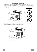
Страница 89: ...GR 8 9 89 1 90 90 4 2 12a 12b...

Страница 90: ...GR 9 0 90 12a...

Страница 91: ...GR 9 1 91 o150 120 mm o120 mm 9 150 9 120 120 150 mm 120 mm 9 8 2 12e 2 9 x 9 5 3 mm...

Страница 92: ...GR 9 2 92...

Страница 93: ...GR 9 3 93 2...

Страница 94: ...GR 9 4 94 Led A 2 B Delay 30 LedB 2 Reset LED 3 Led 100 Led 200 C Led 2 6 Led D Led E Led Off 4 Led 2 Led F Led 2 2 Led 1 Led G Led 2 Off 2 Led G F 1 Led G F H Off On...

Страница 95: ...GR 9 5 95 3 V CR2032 2 Off 2 Delay Delay...

Страница 96: ...GR 9 6 96 Comfort Panel ComfortPanel comfortpanel 2 2 Comfort Panel ComfortPanel...

Страница 97: ...GR 9 7 97 4 5 F 2 2 Led 1 Led 2 comfort panel comfort panel...

Страница 98: ...RU 9 8 98 650 I 120...

Страница 99: ...RU 9 9 99 0 04 8...

Страница 100: ...RU 1 0 100 12 4 5 2 6 kW 5 kW 1 9 kW 1 9 kW 1 kW...

Страница 101: ...RU 1 0 101 1 1 2 1 3 1 4 1 7 1 2 7 2 2 7 3 2 12a 16 3 5 x 9 5 12b 6 M4 x 8 12c 6 4 x 15 1...

Страница 102: ...RU 1 0 102 512 794 520 802 537 880 537 880 512 794 520 802...

Страница 103: ...RU 1 0 103 109 812 3 5...

Страница 104: ...RU 1 0 104 7 2 12a 7 2 12a A A 7 2 12a 2 12c 12c 7 2...

Страница 105: ...RU 1 0 105 7 2 12a 7 2 12a 7 2 12a A 2 12c 12c 7 2...

Страница 106: ...RU 1 0 106 7 1 12a 7 2 2 12c 12a 12c 12a 7 1 12a 7 1...

Страница 107: ...RU 1 0 107 7 3 12b 12c 7 3 12b 7 3 12b 7 3 12c 12c 12b...

Страница 108: ...RU 1 0 108 1 90 4 2 12a 12b...

Страница 109: ...RU 1 0 109 12a...

Страница 110: ...RU 1 1 110 150 120 120 9 150 9 120 120 150 120 9 8 2 12e 2 9 x 9 5 3...

Страница 111: ...RU 1 1 111...

Страница 112: ...RU 1 1 112 2...

Страница 113: ...RU 1 1 113 A 2 B 30 B 2 3 100 200 C 2 6 D E 4 2 F 2 2 B 1 B G 2 2 G F 1 G F H...

Страница 114: ...RU 1 1 114 3 CR2032 2 2...

Страница 115: ...RU 1 1 115 B 2 B 2...

Страница 116: ...B 4 5 F 2 2 B 1 B B 2 RU 116...

Страница 117: ......

Страница 118: ......

Страница 119: ......

Страница 120: ...991 0497 156_ver4 190702 D00003515_03...

Отзывы: