1
2
3.
.
.
1
、
2
、
(
1
)
(
2
)
(
3
)
(
4
)
1
、
2
、
3
、
4
、
5
、
Maintaining the Appliances
Dismantling the Parts
Cleaning the Parts
Please ensure that your appliance is well-maintained in order for it to function properly.
Please disconnect the appliance from the power supply before maintaining the appliance
by pulling out the plug head.
Please wear gloves when maintaining the appliance to avoid getting cut by the components
of the appliance.
To ensure the cleanliness and aesthetics of the appliance, the surface of the appliance
needs to be cleansed of grease frequently.
5
、
A comprehensive maintenance procedure is to be performed once a year in order to
remove grease from all areas and ensure the optimum performance of the appliance.
Please exercise care when dismantling the parts in order to avoid deforming or damaging
the parts.
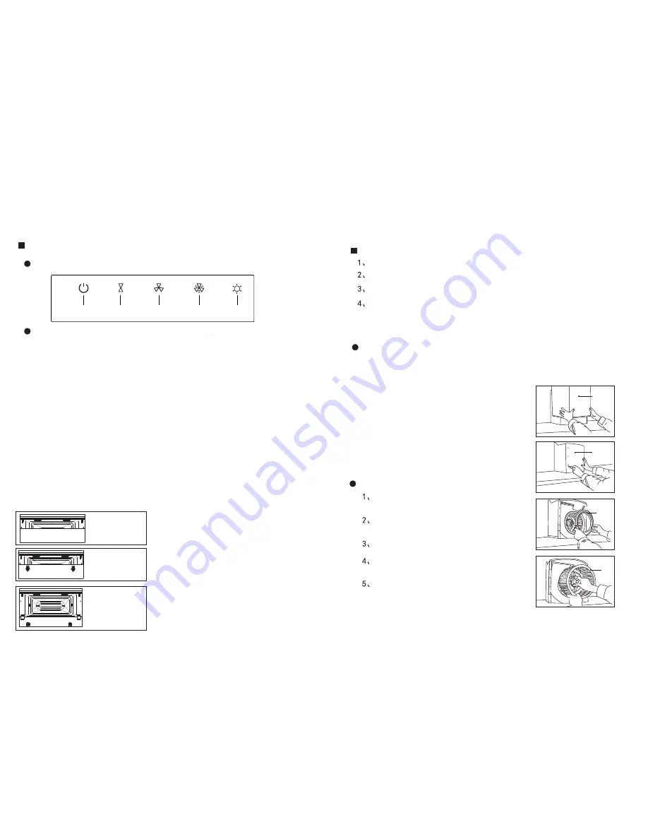
Lower
Chimney
Flue
Cover
Panel
Exhaust
Ring
Impeller
Remove the screws securing the lower chimney flue
(at the rear portion of the appliance) and take down the
chimney flue.
Remove the screws of the cover panel and take down
the cover panel.
Remove the screws securing the exhaust ring and take
down the exhaust ring.
Remove the impeller cap by turning it in the direction
indicated by the arrow shown on the cap and take down
the impeller.
When the maintenance procedure is completed,
reassemble the components in reverse sequence.
The parts should be cleaned with a neutral cleansing
agent and soft cloth or soft brush. Do not use organic
solvents.
It is best to rinse the parts after soaking them for 30
minutes. Please exercise care to avoid deforming or
damaging the parts.
Upon cleaning the parts, please rinse them with water
and dry them with a soft cloth.
Electrical parts are to be cleaned with a dry and
soft cloth or soft brush, and are not to be cleaned
with water or a cleansing agent.
Failure to follow the instructions in this manual might
result in the risk of the cooker hood catching fire.
Using the Appliances
Control Panel (with “ Delay Timer” Function)
Power/
Delay Timer
Light
Low Speed
High Speed Turbo Speed
Operating the Appliances
When the appliance is in “power off” mode, pressing the “power” button would put it in
“standby” mode where the status panel will turn on automatically.
When the appliance is in “standby” mode, pressing the “turbo speed”, “high speed” or
“low speed” button would start the appliance which will operate at the selected mode.
All three speed functions have interlocking features.
Note:
The “turbo speed” function runs for 3 minutes.
After the “turbo speed” function has run for 3 minutes, it will automatically go
back to the “high speed” function.
Under any mode, the “light” button is used to control the light only. Pressing
the button would turn on the lights and pressing it again would turn it off.
Firstly, start the range
hood and open up
the glass panel.
Use both hands to hold
the upper portion of the
glass panel and pull it
downwards to open it.
Use a Philips screwdriver
to dismantle the four
screws securing the
inner filter and take
down the said filter.
When the range hood is running, pressing the currently used button one more
time would turn it off. Pressing the “power” button when the range hood is
running would activate the “delay timer” function for 3 minutes, after which
the range hood will stop running. Pressing the “power” button again when
the “delay timer” function is running for 3 minutes would immediately turn off
the appliance, whereby the panel would shut down automatically and the
appliance will turn off.
Dismantling the Rectifier Panel


