


Version 07/11 - Page 7
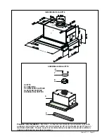
Rangehood Control Panel
All controls are located on the right side of the rangehood.
Light On/Off Switch
TheOn/Off switch for the halogen light is located behind the
front trim. Moving the switch to the 1 Position turns the light
On. Moving the switch to the 0 position turns the light off.
Blower Speed Switch
B in FIGURE 10
shows the speed control switch for the
blower. Moving the switch to the 1 Position turns the blower
on LOW. Moving the switch to the 2 Position turns the blower
on MEDIUM. Moving the switch to the 3 Position turns the
blower on HIGH. Moving the switch to the 0 Position turns
the blower off.
Automatic Operation
As long as the blower and light switches are on, the blower
and light will automatically operate when the visor is opened
and shut off when the visor is closed.
For Best Results
Start the rangehood several minutes before cooking to develop
proper airflow. Allow the unit to operate for several minutes
after cooking is complete to clear all smoke and odors from
the kitchen.
Cleaning
The metal grease filters should be cleaned frequently in hot
detergent solution or placed in the dishwasher. Clean exterior
surfaces with hot soapy water, and use stainless steel cleaner
on the front strip. Using abrasives and scouring agents can
scratch rangehood finishes and should not be used to clean
finished surfaces.
FIGURE 10
FIGURE 7
FIGURE 8
Replacing the Halogen Lamps
Before attempting to replace the lamps, make sure that
the light switch is turned off. Remove the 2 screws
(as
indicated in FIGURE 8)
that hold the light support and
gently pull the support down from the hood. Remove
the lamp from the light support and replace with new
lamp. Replace the light support and fix it into place
with the 2 screws.
An alternative method to replace the lamps is to use a
1 1/4" suction cup (
FIGURE 9
). Attach the suction cup
to the bulb and pull firmly down on the bulb and replace
with a new lamp. The hood uses a
20 Watt MR-11 type
halogen
bulb with a lens cover.
FIGURE 9
EN
1
2
12
CARE
Grease filters
CLEANING METAL SELF- SUPPORTING GREASE FILTERS
• The filters must be cleaned every 2 months of operation, or
more frequently for particularly heavy usage, and can be
washed in a dishwasher.
• Remove the filters one at a time by pushing them towards the
back of the group and pulling up at the same time.
• Wash the filters, taking care not to bend them. Allow them to
dry before refitting.
• When refitting the filters, make sure that the handle is visible
on the outside.
Activated charcoal filter (Recirculating version)
These filters (not supplied with the rangehood)are not washable
and cannot be regenerated, and must be replaced approximately
every 4 months of operation, or more frequently with heavy us-
age.
REPLACING THE ACTIVATED CHARCOAL FILTER
• Remove the metal grease filters
• Remove the saturated activated charcoal filter as shown (
A
).
• Fit the new filters (
B
).z
• Replace the metal grease filters.
�
�
Lighting
LIGHT REPLACEMENT
20 W halogen light.
• Remove the 2 screws fixing the Lighting support, and pull it
out of from the Hood.
• Extract the lamp from the Support.
• Replace with another of the same type, making sure that the
two pins are properly inserted in the lamp holder socket holes.
• Replace the Support, fixing it in place with the two screws re-
moved as above.
EN
1
1
11
USE
Control board
L
Light
Switches the lighting system on and off.
M
Motor Switches the extractor motor on and off.
V
Speed Sets the operating speed of the extractor:
1. Low speed, used for a continuous and silent air change in the presence of
light cooking vapour.
2. Medium speed, suitable for most operating conditions given the optimum
treated air flow/noise level ratio.
3. Maximum speed, used for eliminating the highest cooking vapour emission,
including long periods.
�
�����
�
�
�
�
�
�
EN
1
2
12
CARE
Gre
ase
filt
ers
CLE
ANI
NG
M
ETA
L S
ELF
- S
UPP
ORT
ING
G
REA
SE
FIL
TER
S
• T
he
filt
ers
m
ust
be
clea
ned
ev
ery
2
mon
ths
of
op
era
tio
n, o
r
mor
e f
req
uen
tly
fo
r p
arti
cul
arly
h
eav
y u
sag
e,
and
c
an
be
was
hed
in
a d
ish
was
her
.
• R
em
ove
th
e fi
lter
s o
ne
at a
tim
e b
y p
ush
ing
th
em
to
war
ds
the
bac
k o
f th
e g
rou
p an
d p
ulli
ng u
p at
the
sam
e ti
me.
• W
ash
th
e fi
lter
s, t
akin
g c
are
no
t to
be
nd
the
m. A
llo
w th
em
to
dry
be
for
e re
fitt
ing
.
• W
hen
re
fitt
ing
th
e fi
lter
s, m
ake
su
re
tha
t th
e h
and
le
is
visi
ble
on
the
ou
tsid
e.
Act
iva
ted
cha
rco
al f
ilte
r (R
eci
rcu
lat
ing
ver
sio
n)
The
se
filt
ers
(no
t s
upp
lie
d w
ith
th
e ra
nge
hoo
d)a
re
not
w
ash
abl
e
and
ca
nno
t b
e re
gen
era
ted
, a
nd
mus
t b
e re
pla
ced
ap
pro
xim
atel
y
eve
ry
4 m
ont
hs
of o
per
atio
n, o
r m
ore
fr
equ
ent
ly
with
he
avy
us
-
age
.
REP
LAC
ING
TH
E A
CTI
VAT
ED
CHA
RCO
AL
FIL
TER
• Re
mov
e the
m
etal
gre
ase
filte
rs
• R
em
ove
th
e sa
tur
ated
ac
tiv
ated
ch
arc
oal
filt
er a
s sh
own
(
A
).
• Fit
the
ne
w filte
rs (
B
).z
• R
epl
ace
th
e m
etal
gr
eas
e fi
lter
s.
�
�
Lig
htin
g
LIG
HT
REP
LAC
EM
ENT
20
W h
alo
gen
lig
ht.
• R
em
ove
th
e 2
sc
rew
s fi
xin
g th
e L
igh
tin
g s
upp
ort,
and
pu
ll i
t
out
of
fro
m th
e H
ood
.
• E
xtra
ct t
he l
am
p fr
om
th
e S
upp
ort.
• R
epl
ace
w
ith
an
oth
er
of
the
sa
me
typ
e, m
aki
ng
sur
e th
at t
he
two
pin
s ar
e p
rop
erly
ins
erte
d in
the
lam
p h
old
er s
ock
et h
ole
s.
• R
epl
ace
th
e S
upp
ort,
fix
ing
it
in
pla
ce
with
th
e tw
o sc
rew
s re
-
mov
ed
as a
bov
e.
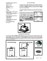
GREASE FILTER REMOVAL
The grease filters are removed by pressing the handle on
the right side of the filter
(FIGURE 7)
. When replacing,
make sure that the filters are properly positioned with
the handles on the right and visible. There are 2 grease
filters, one in the slide out part of the hood, the other in
the back.
USE AND CARE INFORMATION
B