Faber Chloe Скачать руководство пользователя страница 14

14

14

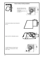
A. Home power supply cable
B. Black wires
C. UL listed wire connectors
D. White wires
E. Green (or bare) ground wire from home power supply connected to green ground screw
F.  Range hood power supply cable
G. Green ground wire from Range hood power supply cable connected to green ground screw.

E

A

F

D

C

B

G

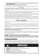
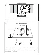
Installation of wiring connection

5HPRYHWKHFRYHUIURPWKH¿HOGZLULQJFRPSDUWPHQW

DO NOT turn on the power until installation is complete! 
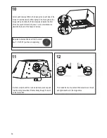
Connect the Power Supply Cable to the rangehood.
Connect the Green (Green and Yellow) ground wire under the Green grounding 
screw. Attach the White lead of the power supply to the White lead of the range-
hood with a twist-on type wire connector. 
Attach the Black lead of the power supply to the Black lead of the rangehood 
with a twist-on type wire connector.

5HSODFHWKH¿HOGZLULQJFRPSDUWPHQWFRYHU

Содержание Chloe

Страница 1: ...CHLO28BK600 CHLO28GR600 Installation Instructions Use and Care Information Instructions d installation Utilisez et d entretien Instrucciones de instalaci n Informaci n de uso y cuidado CHLOE...

Страница 2: ...XNTQ A BJ SN M DWHS Based on Kitchen Firesafety Tips published by NFPA WARNING TO REDUCE THE RISK OF FIRE OR ELECTRIC SHOCK do not use this fan with any solid state speed control device WARNING TO RED...

Страница 3: ...KC AD HMRS KKDC SN LHMHLHYD A BJV QC BNKC HQ kNV MC nonmetallic thermal break should be installed to minimize conduction of outside temperatures as part of the vent system The damper should be on the...

Страница 4: ...should be connected directly to the fused disconnect or circuit breaker through kDWHAKD QLNQDC NQ MNMLDS KKHB RGD SGDC BNOODQ B AKD KKNV RNLD RK BJ HM SGD B AKD RN SGD OOKH MBD B M AD LNUDC HE RDQUHBH...

Страница 5: ...5 RANGEHOOD DIMENSIONS 7 11 16 7 11 16 REAR DUCTED VENTING INSTALLATION SGD NNC RGNTKC BNLD RDS HM SGHR ONRHSHNM...

Страница 6: ...6 Min 24 Min 30...

Страница 7: ...ry REMCTRL Cfm reducer kit 600 400 sk CFMRED 2 Cfm reducer kit 600 300 sku CFMRED Parts needed 6 Round Metal ductwork MAIN PARTS Components Ref Qty Product Components 1 1 HoodBody completewith Con tro...

Страница 8: ...purchase of Activated Charcoal Accessory Horizontal Vertical 6 When used in recirculation mode To Reduce the Risk of Fire and Shock use only conversion kit Model FILTER1 Rear Requires purchase of Chim...

Страница 9: ...A 11 9 16 above the horizontal line and at 4 5 16 distance on the left and right of vertical line Checking that the two marks are level Insert two wall plugs and screws purchased separately into the A...

Страница 10: ...wo lower screws purchased separately 4 L 2x L 2x 5 Open the panel unlock the security cable as VKRZQ 5HPRYH WKH OWHUV E SXVKLQJ WKH OHYHU towards the back of the unit and at the same time pulling down...

Страница 11: ...nect the left and right Connectors from the blower 6 Unscrewthe2screws Posi Drive thathold theblowerandunlockit fromtheinitialpositionas showninImagea E F D G Afterremovingblower rotateasshownuntiliti...

Страница 12: ...U 3UHVV WKH FKDUFRDO OWHU WLJKWO WR WKH EODFN JULG RQ WKH EORZHU VLGH DQG URWDWH WKH OWHU FORFNZLVH WRZDUGV WKH IURQW of the hood until it locks into place Turn counterclockwise towards the back of th...

Страница 13: ...e Wiring Box to connect the Hood to Power Supply Cable Pull the cable from the Power Supply through the Hole for the Electrical Connection to the Wiring Box Remove the Wiring Box compartment cover by...

Страница 14: ...wiring connection 5HPRYH WKH FRYHU IURP WKH HOG ZLULQJ FRPSDUWPHQW DO NOT turn on the power until installation is complete Connect the Power Supply Cable to the rangehood Connect the Green Green and...

Страница 15: ...wn in the image with the 2 Screws 12b 12b Attention After the Wiring Box installation place the Cable inside a Rear Section without stressing for the Cable 12a Screw the two 12a screws into the Rear S...

Страница 16: ...plifytheconnect ofAiroutletduct E F D G Only for the Rear Ducting Installation Usethisdimensionaldrawingtohelpwithplanningofduct connection Install to the Roof or Wall attach ductwork After LQJ WKH RG...

Страница 17: ...he lower holes on the Rear Section Secure all the 4 screws 18 M1 4x M6x15 M1 4x 19 5HSODFH WKH OWHUV LQWR WKH KRRG DQG ORFN WKH security cable as shown in the image to the right Close the panel 17 Hoo...

Страница 18: ...LQVLGH WKH KRRG XVH D DW KHDG VFUHZGULYHU DV shown in image above to disconnect the left and right Connectors from the blower 1 2 3 Open the panel unlock the security cable as shown 5HPRYH WKH OWHUV E...

Страница 19: ...19 4 Pull the Cable from the rear hole Fix the Cable in the hole on the Top of the Hood as show Move the Cable from the rear of the Hood to the Top of the Hood...

Страница 20: ...ly 6 5 Unscrewthe2screwsthatholdtheblowerandunlockitfromtheinitialpositionasshowninImagea E F D G AfterremovingblowerrotateasshownuntilitisinthecorrectrearventingpositionasshowninImageb c Usethetwoscr...

Страница 21: ...RUL RQWDO OLQH DW ZKHUH WKH ERWWRP HGJH RI WKH KRRG ZLOO EH ORFDWHG DV LQGLFDWHG LQ WKH JXUH WKDW LV D PLQLPXP of 24 above Electric cooking surface and 30 above Gas A10 A 1 0 From inside the hood re c...

Страница 22: ...rksarelevel Inserttwowallplugs purchasedseparately Placeabracket7 2 1onthewallasshownabout11 8 fromtheceilingorupperlimit aligningthecenter notch withtheverticalreferencelineand markthewallatthecenter...

Страница 23: ...the 4 screws 12a L 2x 4 L 4x 11 12 Use the four screws included with Optional Tele scopic Chimney Kit to secure the angle bracket 13 8 L 4x M 2x Fix the bracket using the screws included with Optional...

Страница 24: ...l ductwork to the Roof or Wall Cap and then attach ductwork N1 10 B 11 N1 M1 4x B Slightly widen the two sides of the upper chimney and hook them behind the brackets making sure that they are well sea...

Страница 25: ...h the Black lead of the power supply to the Black lead of the rangehood with a twist on type wire connector 5HSODFH WKH HOG ZLULQJ FRPSDUWPHQW FRYHU 17 A Home power supply cable B Black wires C UL lis...

Страница 26: ...proximately3seconds withalltheloadsturnedoff MotorandLights WR SHUIRUP D UHVHW 7KH 6 DVKHV WKUHH WLPHV Flashing T4 Turns the Motor on at INTENSIVE Speed This speed is timed to run for 6 minutes At the...

Страница 27: ...FRORU RYHU WLPH WKLV ZLOO KDYH DEVROXWHO QR HIIHFW RQ LWV HI FLHQF Replace taking care to ensure that the handle faces forward OHDQLQJ LQ GLVKZDVKHU PD GXOO WKH QLVK RI WKH PHWDO JUHDVH OWHU Replacin...

Страница 28: ...28 Wiring Diagram U B...

Страница 29: ...om accident alteration misuse abuse fire flood acts of God improper installation installation not in accordance with electrical or plumbing codes or Faber documentation or use of products not approved...

Страница 30: ...u OTAKH O Q K TW S SR 4MHR AVERTISSEMENT POURR DUIRELERISQUED INCENDIEOUDECHOC LECTRIQUE n utilisez jamaisceventilateurenassociationavecundispositifder glagedevitesse semi conducteurs AVERTISSEMENT PO...

Страница 31: ...TQ CT BK ODS K MfDRS O R QDBNLL MC CfTSHKHRDQ CDR BNMCTHSR lDWHAKDR DR BNMCTHSR lDWHAKDR OQNUNPTDMS TMD BNMSQD OQDRRHNM DS CD K STQATKDMBD PTH CHLHMTDMS FQ MCDLDMS KfDEkB BHS CD Kf OO QDHK RRTQDY UNTR...

Страница 32: ...D NT T CHRINMB SDTQ O Q TM B AKD kDWHAKD CD BTHUQD UDB AKHMC FD NT F HMD MNM L S KKHPTD HRRDY TM ODT CD IDT C MR KD B AKD ONTQ ODQLDSSQD KD C OK BDLDMS CD Ke OO QDHK RH CDR SQ U TW CeDMSQDSHDM Re U Q...

Страница 33: ...33 DIMENSIONS DE LA HOTTE 7 11 16 7 11 16 INSTALLATION AVEC VENTILATION CANALIS E ARRI RE K GNSSD CDUQ HS SQD KHUQ D UDB BDSSD BNMkFTQ SHNM...

Страница 34: ...34 Min 24 Min 30...

Страница 35: ...LUH 5 0 75 R ducteur de d bit 600 400 no d article CFMRED 2 R ducteur de d bit 600 300 no d article CFMRED Pi ces requises Conduit m tallique 6 circulaire PI CES PRINCIPALES Composants R f Qt Composan...

Страница 36: ...actif Horizontale Verticale 6 Pour r duire le risque d incendie ou de choc lectrique lorsque l appareil est utilis en mode recyclage utiliser uniquement le mod le FILTER1 en guise de trousse de conve...

Страница 37: ...iqu A 11 9 16 au dessus de la ligne horizontale et la distance de 4 5 16 GURLWH HW j JDXFKH GH OD OLJQH YHUWLFDOH 9pUL H VL OHV GHX PDUTXHV VRQW j pJDOLWp Ins rez deux chevilles et les vis achet es s...

Страница 38: ...achet es s par ment 4 L 2x L 2x 5 Ouvrez le panneau et d gagez le c ble de retenue comme illustr Retirez les OWUHV HQ SRXVVDQW VLPXOWDQpPHQW OH OHYLHU vers l arri re de l appareil et en le tirant YHUV...

Страница 39: ...6 D vissez les 2 vis Posi Drive qui retiennent le ventilateur et d verrouillez le de sa position initiale comme illustr sur l image A E F D G Apr s avoir retir le ventilateur tournez le FRPPH LOOXVWU...

Страница 40: ...UERQ FRQWUH OD JULOOH QRLUH GH FKDTXH F Wp GX YHQWLODWHXU HW IDLWHV WRXUQHU OH OWUH dans le sens des aiguilles d une montre vers l avant de la hotte MXVTX j FH TX LO VRLW YHUURXLOOp HQ SODFH DLWHV WRX...

Страница 41: ...n pour brancher le c ble reliant la hotte l alimentation Tirez le c ble de l alimentation par le trou permettant le raccord lectrique du bo tier de connexion Retirez le couvercle du compartiment du bo...

Страница 42: ...des branchements Retirez le couvercle du compartiment des c blages externes NE METTEZ PAS l alimentation sous tension avant d avoir termin l installation Branchez le c ble d alimentation la hotte UDQF...

Страница 43: ...ur l image l aide des 2 vis 12b 12b Attention Apr s l installation du bo tier de connexion placez le c ble dans une section arri re sans contrainte sur le c ble 12a Vissez les deux vis 12a dans la sec...

Страница 44: ...tie d air E F D G Pour l installation avec canalisation arri re uniquement 8WLOLVH FH SODQ GLPHQVLRQQHO SRXU YRXV DLGHU j SODQL HU OH raccord des canalisations Raccordez le dispositif aux canalisation...

Страница 45: ...ieurs sur la section arri re Vissez les 4 vis 18 M1 4x M6x15 M1 4x 19 5HPHWWH OHV OWUHV HQ SODFH GDQV OD KRWWH et verrouillez le c ble de retenue comme illustr dans l image droite Refermez le panneau...

Страница 46: ...ieur de la hotte utilisez un tournevis lame plate comme illustr pour d brancher les connecteurs de gauche et de droite du ventilateur 1 2 3 Ouvrez le panneau et d gagez le c ble de retenue FRPPH LOOXV...

Страница 47: ...47 4 Tirez le c ble du trou arri re Fixez le c ble dans le trou du haut de la hotte comme illustr D placez le c ble de l arri re de la hotte vers le haut de la hotte...

Страница 48: ...ur et d verrouillez le de sa position initiale comme illustr sur l image A E F D G SUqV DYRLU UHWLUp OH YHQWLODWHXU WRXUQH OH FRPPH LOOXVWUp MXVTX j TX LO VH WURXYH GDQV OD SRVLWLRQ FRUUHFWH GH ventil...

Страница 49: ...u bas de la hotte comme repr sent dans l illustration Cet emplacement doit se trouver au moins 24 de la surface de cuisson si elle est lectrique ou 30 si elle est au gaz A10 A 1 0 Depuis l int rieur d...

Страница 50: ...deux chevilles achet es s par ment Placez une bride 7 2 1 sur le mur comme illustr environ 1 1 8 du plafond ou de la limite sup rieure en alignant le centre encoche avec la ligne de r f rence vertica...

Страница 51: ...L 2x 4 L 4x 11 12 Utilisez les quatre vis incluses avec la trousse de chemin e t lesco pique en option SRXU HU O pWULHU d assemblage 13 8 L 4x M 2x Fixez l trier l aide des vis incluses avec la trouss...

Страница 52: ...allique de 6 au clapet de toiture ou au clapet mural puis raccordez les conduits N1 10 B 11 N1 M1 4x B eFDUWH OpJqUHPHQW OHV GHX F WpV GH OD FKH min e sup rieure et engagez les l arri re des brides en...

Страница 53: ...estique B Fils noirs 6HUUH OV KRPRORJXp 8 D Fils blancs LO GH PLVH j OD WHUUH YHUW RX O QX GH O DOLPHQWDWLRQ GRPHVWLTXH EUDQFKp j OD YLV GH PLVH la terre verte F C ble d alimentation de la hotte G Fil...

Страница 54: ...Appuyez sur ce bouton et tenez le enfonc pendant environ 3 secondes lorsque tous les dispositifssont teints moteuret clairage pourr initialiser Let moinDELS1clignotetroisfois Clignotant T4 Allume le...

Страница 55: ...VRQ HI FDFLWp Remettez le en place en vous assurant que la poign e se trouve vers l avant H ODYH YDLVVHOOH SRXUUDLW WHUQLU OH QL GX OWUH j JUDLVVH PpWDOOLTXH 1DLOK BDLDMS CT kKSQD BG QANM BSHE Il ne p...

Страница 56: ...56 Sch ma de c blage U B...

Страница 57: ...om accident alteration misuse abuse fire flood acts of God improper installation installation not in accordance with electrical or plumbing codes or Faber documentation or use of products not approved...

Страница 58: ...hacia una salida Basado en Consejos para luchas contra los incendios en las cocinas publicado por NFPA ADVERTENCIA PARAREDUCIRELRIESGODEDESCARGASEL CTRICASOINCEN DIOS nouseesteventiladorconning ndispo...

Страница 59: ...HRHSNR CD UDMSHK BH M OTDCD OQNUNB Q TM HMBDMCHN ADVERTENCIA Instalaciones en clima fr o 2D CDAD HMRS K Q TM QDFHRSQN CD SHQN CHBHNM K O Q LHMHLHY Q DK kTIN CD HQD EQ N G BH SQ R X RD CDAD HMRS K Q TM...

Страница 60: ...RSHBN CDAD BNMDBS QRD CHQDBS LDMSD K CDRBNMDWH M ONQ ETRHAKD N CHRXTMSNQ SQ U R CD TM B AKD kDWHAKD AKHMC CN N MN LDS KHBN CD BNAQD DMETMC CN DID KFN CD SDMRH M DM DK B AKD O Q ONCDQ LNUDQ DK CHRONRH...

Страница 61: ...61 DIMENSIONES DE LA CAMPANA 7 11 16 7 11 16 INSTALACI N DE VENTILACI N DE CONDUCTOS TRASEROS K B LO A CDADQ UDMHQ DM DRS ONRHBH M...

Страница 62: ...62 M n 24 M n 30...

Страница 63: ...400 sku CFMRED 2 Kit reductor Cfm 600 300 sku CFMRED Piezas necesarias Conducto met lico redondo 6 PARTES PRINCIPALES Componentes Ref Cdad Componentes del producto 1 1 Cuerpodelacampana completode Con...

Страница 64: ...ULR GH FDUEyQ activado Horizontal Vertical 6 Cuando se utiliza en el modo de recircu ODFLyQ SDUD UHGXFLU HO ULHVJR GH LQFHQGLR GHVFDUJD HOpFWULFD XWLOLFH VyOR HO NLW GH FRQYHUVLyQ 0RGHOR 7 5 Trasero R...

Страница 65: ...l y a una distancia de 4 5 16 a la izquierda y la derecha de la l nea vertical Comprobando que las dos marcas est n niveladas QVHUWH GRV WDSRQHV GH SDUHG WRUQLOORV VH FRPSUDQ SRU VHSDUDGR HQ ORV RUL F...

Страница 66: ...dos tornillos inferiores se compran por separado 4 L 2x L 2x 5 Abra el panel desbloquee el cable de seguridad como se muestra Quite los OWURV HPSXMDQGR OD SDODQFD KDFLD OD SDUWH posterior de la unidad...

Страница 67: ...6 Desatornille los 2 tornillos Posi Drive que sostienen el ventilador y desbloqu elo GHVGH OD SRVLFLyQ LQLFLDO como se muestra en la Imagen a E F D G Despu s de retirar el ventilador gire como se mue...

Страница 68: ...yQ UPHPHQWH FRQWUD OD UHMLOOD QHJUD HQ HO ODGR GHO VRSODGRU JLUH HO OWUR HQ VHQWLGR horario hacia la parte delantera de la campana hasta que HQFDMH HQ VX OXJDU LUH HQ VHQWLGR DQWLKRUDULR KDFLD OD SDUW...

Страница 69: ...ctar la campana al cable de suministro de energ a Tire del cable de suministro GH HQHUJtD D WUDYpV GHO RUL FLR SDUD OD FRQH LyQ HOpFWULFD D OD FDMD GH FDEOHDGR Retire la cubierta del FRPSDUWLPLHQWR GH...

Страница 70: ...alaci n de conexi n de cableado Retire la tapa del compartimento de cableado de campo 12 HQFLHQGD OD XQLGDG KDVWD TXH VH KD D FRPSOHWDGR OD LQVWDODFLyQ RQHFWH HO FDEOH GH OD IXHQWH GH DOLPHQWDFLyQ D O...

Страница 71: ...la imagen con los 2 tornillos 12b 12b Atenci n HVSXpV GH OD LQVWDODFLyQ GH OD FDMD GH FDEOHDGR FRORTXH HO FDEOH GHQWUR GH XQD VHFFLyQ posterior sin tirarlo demasiado 12a Atornille los dos tornillos 12...

Страница 72: ...WR GH VDOLGD de aire E F D G Solo para la instalaci n de conducto trasero 8WLOLFH HVWH GLEXMR GLPHQVLRQDO SDUD D XGDU FRQ OD SODQL FDFLyQ GH OD FRQH LyQ GHO FRQGXFWR QVWDOH HQ HO FRQGXFWR GH FRQH LyQ...

Страница 73: ...HFFLyQ SRVWHULRU Asegure los 4 tornillos 18 M1 4x M6x15 M1 4x 19 9XHOYD D FRORFDU ORV OWURV HQ OD FDPSDQD y bloquee el cable de seguridad como se muestra en la imagen a la derecha Cierre el panel 17 E...

Страница 74: ...un destornillador de cabeza plana como se muestra en la imagen de arriba para desconectar los conectores izquierdo y derecho del ventilador 1 2 3 Abra el panel desbloquee el cable de seguridad FRPR V...

Страница 75: ...re del cable desde HO RUL FLR WUDVHUR LMH HO FDEOH HQ HO RUL FLR HQ OD SDUWH superior de la campana como se muestra Mueva el cable desde la parte posterior de la campana hasta la parte superior de la...

Страница 76: ...WLODGRU GHVEORTXpHOR GHVGH OD SRVLFLyQ LQLFLDO FRPR VH PXHVWUD HQ OD Imagen a E F D G HVSXpV GH UHWLUDU HO YHQWLODGRU JLUH FRPR VH PXHVWUD KDVWD TXH HVWp HQ OD SRVLFLyQ FRUUHFWD GH YHQWLODFLyQ WUDVHUD...

Страница 77: ...VH XELFDUi HO ERUGH LQIHULRU GH OD FDPSDQD FRPR VH LQGLFD HQ OD JXUD TXH HVWi D XQ PtQLPR GH VREUH OD VXSHU FLH GH FRFFLyQ HOpFWULFD VREUH OD GH JDV A10 A 1 0 Desde el interior de la campana vuelva a...

Страница 78: ...Inserte dos tapones de pared se compran por separado Coloque un soporte 7 2 1 en la pared como se muestra a aproximadamente 1 1 8 del techo o l mite superior alinee el centro PXHVFD FRQ OD OtQHD GH U...

Страница 79: ...illos 12a L 2x 4 L 4x 11 12 Utilice los cuatro tornillos incluidos con el kit de chi PHQHD WHOHVFySLFD RSFLRQDO SDUD MDU el soporte angular 13 8 L 4x M 2x LMH HO VRSRUWH utilizando los tornillos que s...

Страница 80: ...cos de 6 al techo o a la tapa de pared y luego conecte los conductos N1 10 B 11 N1 M1 4x B Ligeramente ensanche los dos lados de la chimenea superior y eng nchelos detr s de los soportes asegur ndose...

Страница 81: ...QWDFLyQ DO FDEOH QHJUR de la campana con un conector de cable tipo twist on Reemplace la cubierta del compartimento de cableado de campo 17 A Cable de la fuente de alimentaci n dom stica B Cables negr...

Страница 82: ...ERWyQ GXUDQWH DSUR LPDGDPHQWH VHJXQGRV FRQ WRGDV ODV FDUJDV apagadas Motor y luces para realizar un reinicio El LED S1 parpadea tres veces Destellando T4 Enciende el motor a velocidad INTENSIVA VWD YH...

Страница 83: ...ing n efecto sobre su H FLHQFLD Reemplace asegur ndose de que el asa est orientada hacia adelante D OLPSLH D HQ HO ODYDYDMLOODV SXHGH HVWURSHDU HO DFDEDGR GHO OWUR GH JUDVD PHWiOLFR 1DDLOK YN CDK kKSQ...

Страница 84: ...84 Diagrama de cableado U B...

Страница 85: ...om accident alteration misuse abuse fire flood acts of God improper installation installation not in accordance with electrical or plumbing codes or Faber documentation or use of products not approved...

Страница 86: ...86...

Страница 87: ...87...

Страница 88: ...991 0527 958_01 180319 D00004610_00...

Отзывы: