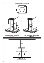
Faber BELAIS48SS600 Скачать руководство пользователя страница 32

32

12

11

Pour installation sans conduit uniquement

De la même façon, placez la section inférieure de la cheminée et fixez la partie inférieure au 

châssis à l'aide des 2 vis enlevées précédemment.

Version 02/12 - Page 8

FIGURE 13

MAKE THE ELECTRICAL CONNECTION

Remove the cover from the field wiring compartment. 

(SEE 

FIGURE 11)


DO NOT turn on the power until installation is 

complete!  

Connect the Power Supply Cable to the rangehood.  

Connect the Green (Green and Yellow) ground wire under the 

Green grounding screw.  Attach the White lead of the power 

supply to the White lead of the rangehood with a twist-on type 

wire  connector.   Attach  the  Black  lead  of  the  power  supply 

to the Black lead of the rangehood with a twist-on type wire 

connector.  

1.

    The  UPPER  CHIMNEY 

COVER 

(C in FIGURE 13)


attaches to the top of the 

support structure using two 

screws provided (

G in FIGURE 

13

).  If using the 

High Ceiling 

Chimney Kit

, use the UPPER 

CHIMNEY  COVER  supplied 

with the kit.  Slide up and 

attach the UPPER CHIMNEY 

COVER. 

2.  Attach the duct work to the 

DAMPER (

M in FIGURE 1

).  

Make sure to seal all joints with 

duct tape to prevent leaks. 

3.

    The  LOWER  CHIMNEY 

COVER 

(B in FIGURE 13)


attaches using two screws 

provided (

G in FIGURE 13

).  

Install the LOWER CHIMNEY 

COVER by sliding it up over 

the support and the UPPER 

CHIMNEY COVER.

For ductless installations, line up the DUCTLESS DIVERTER 

EXTENSIONS HORIZONTAL 

(B in FIGURE 12) 

with the holes 

in the LOWER CHIMNEY COVER 

(D in FIGURE 12)

 and snap 

in the  VENT GRIDS 

(C in FIGURE 12)

.

INSTALLING THE RANGEHOOD

A. Home power supply cable

B. Black wires

C. UL listed wire connectors

D.White wires

E. Green (or bare) ground wire from home power supply 

connected to green ground screw

F. Range hood power supply cable

G.Range hood power supply cable connected to green 

ground screw

FIGURE 11

Ductless installations require 

Ductless Conversion 

Kit

 whose components are 

pictured in 

FIGURE 12

.  Do 

not use the DAMPER  (

in FIGURE 1

)  for ductless 

installations.


The LOWER 

CHIMNEY  COVER 

(B 

in FIGURE 1)

 should be 

discarded and replaced by 

the new one with holes from 

the 

Ductless Conversion Kit


(D in FIGURE 12)

.

As indicated in 

FIGURE 

12

,  place  the  DUCTLESS 

DIVERTER 

(A) 

over  the  

exhaust opening of the  EASY 

CUBE  

(E)

.  Fit the DUCTLESS 

DIVERTER  EXTENSIONS 

HORIZONTAL 

(B) 

into the


DIVERTER

 (A).

FIGURE 12

FOR DUCTLESS INSTALLATIONS

L'installation sans conduit nécessite une 

Trousse de conversion pour 

installation sans conduit 

dont les 

éléments sont représentés à la 

FIGURE 

11

N'utilisez pas le REGISTRE pour 

l'installation sans conduit. L'HABILLAGE 

INFÉRIEUR DE CHEMINÉE doit être 

remplacé par celui présentant des trous 

de la 

Trousse de conversion pour 

installation sans conduit (D sur 

la FIGURE 11)

.

Tel qu'indiqué sur la 

FIGURE 11

, placez 

le DÉFLECTEUR DE RECYCLAGE (

A

) sur 

l'ouverture d'évacuation du EASY CUBE 

(

E

). Placez les SORTIES HORIZONTALES 

DU DÉFLECTEUR DE RECYCLAGE (

B

dans le DÉFLECTEUR (

A

).

Содержание BELAIS48SS600

Страница 1: ...0 B BELAIS42SS600 B BELAIS48SS600 BELLA IS 36 42 48 Installation Instructions Use and Care Information Instructions d installation Utilisez et d entretien Instrucciones de instalaci n Informaci n de u...

Страница 2: ...with your back to an exit Based on Kitchen Firesafety Tips published by NFPA WARNING TO REDUCE THE RISK OF FIRE OR ELECTRIC SHOCK do not use this fan with any solid state speed control device WARNING...

Страница 3: ...DO NOT terminate the ductwork in an attic or other enclosed space DO NOT use 4 laundry type wall caps Flexible type ductwork is not recommended DO NOT obstruct the flow of combustion and ventilation a...

Страница 4: ...opper cable Allow some slack in the cable so the appliance can be moved if servicing is ever necessary A UL Listed 1 2 conduit connector must be provided at each end of the power supply cable at the a...

Страница 5: ...5 RANGEHOOD DIMENSIONS 0LQ 0D 0LQ 0D 0LQ 0D 0LQ 0D Min 24 Min 30 Non Ducted Recirculation DUCT2 Ducted Venting...

Страница 6: ...4 x 3 1 8 12c 2 Screws 1 8 x 1 4 12e 4 Screws 1 8 x 3 8 12q 4 Screws 1 4 x 9 16 21 1 Drilling template 22 4 1 4 int dia washers 23 4 1 4 Nuts Qty Documentation 1 Instruction Manual Available Accessori...

Страница 7: ...Option Ducted Venting Options Installation Requires Ductless Accessory Kit purchased separately 6 K OK 3 16 T OK 3 16 OK 3 16 Components for installation to the ceiling These fasteners may need to be...

Страница 8: ...Supply Cable Use caulking to seal around the hole A knockout for threading through the Power Supply from the ceiling is located on the top of the frame Do not connect the Power Cable to the Wiring Box...

Страница 9: ...wer frame If you need to adjust the height of the frame proceed as follows Unfasten the metric screws joining the two columns located at the sides of the frame 1 2 3 4 5 6 Adjust the frame to the heig...

Страница 10: ...TE The chimney structure can reduce down to a 27 minimum height To reduce the height the middle section of the support structure needs to be removed Out of the box the minimum chimney length is 32 Ins...

Страница 11: ...ough the strain relief Next position the chimney support so that the large end of the keyhole slots are over the ceiling attachment screws or bolts Then push the chimney support so that the bolts are...

Страница 12: ...upply to the Black lead of the rangehood with a twist on type wire connector 1 The UPPER CHIMN COVER C in FIGURE attaches to the top of support structure using screwsprovided GinFIGU 13 If using the H...

Страница 13: ...up and attach the UPPER CHIMNEY COVER 2 Attach the duct work to the DAMPER M in FIGURE 1 Makesuretosealalljointswith duct tape to prevent leaks 3 The LOWER CHIMNEY COVER B in FIGURE 13 attaches using...

Страница 14: ...filters from the hood canopy Remove any activated charcoal filters Working from below fix the hood canopy to the frame where indicated using the 4 screws 12f then tighten all the screws securely Atta...

Страница 15: ...Connect the lights connector Lux Placetheconnectorsinthejunctionbox24and close it using the 4 screws provided 15 12c x 2 Fix the junction box to the hood body using the 2 screws 12c provided H Make th...

Страница 16: ...al Filter Accessory sku FILTER2 purchased separately Attach a charcoal filter in the correct position and block it by the fixing hooks as shown Unlock the fixing hooks towards the back of the insert h...

Страница 17: ...ry second while the motor is running It is disabled by pressing the button When the filters alarm is triggered the alarm can be reset by pressing and holding this button for approximately 3 seconds Th...

Страница 18: ...orwards Nowatercanbepresentinfiltersbeforeinstallingbackinhood Replacing Activated Charcoal Filter Itcannotbewashedorregenerated andmustbechangedwhen the FC symbol on the display appears or at least o...

Страница 19: ...19 Wiring Diagram 991 0442 621 H90 308 r1 D002937_00 120V 60Hz...

Страница 20: ...om accident alteration misuse abuse fire flood acts of God improper installation installation not in accordance with electrical or plumbing codes or Faber documentation or use of products not approved...

Страница 21: ...e se trouve derri re vous pendant que vous teignez les flammes D apr s le guide Kitchen Firesafety Tips publi par la NFPA aux tats Unis AVERTISSEMENT POURR DUIRELERISQUED INCENDIEOUDECHOC LECTRIQUE n...

Страница 22: ...une meilleure efficacit la longueur des conduits et le nombre de coudes doivent tre le pluslimit squepossible Lediam tredesconduitsdevrait treuniforme N installezpasdeuxcoudes ensemble Utilisez un ru...

Страница 23: ...ermettre le d placement de l appareil si des travaux d entretien s av raient n cessaires Un raccord de conduit homologu par l UL de 1 2 doit tre install aux deux extr mit s du c ble d alimentation au...

Страница 24: ...24 DIMENSIONS DE LA HOTTE 0LQ 0D 0LQ 0D 0LQ 0D 0LQ 0D Min 24 Min 30 Sans canalisation recirculation DUCT2 Installation avec ventilation canalis e...

Страница 25: ...1 8 x3 8 12q 4 Vis1 4 x9 16 21 1 Gabaritdeper age 22 4 Rondellesdiaint 1 4 23 4 crous1 4 Qt Documentation 1 Moded emploi Trousse de chemin e pour plafonds hauts pour remplacer le conduit sup rieur de...

Страница 26: ...tion Option de recirculation Options d installation avec ventilation canalis e Exige la trousse d accessoires sans conduit achet e s par ment Composants d installation au plafond Il pourrait tre n ces...

Страница 27: ...ble d alimentation Utiliser un calfeutrage pour sceller autour du trou Une pi ce d foncer pour le passage de l alimentation lectrique du plafond est situ e au sommet du ch ssis Ne branchez pas le c b...

Страница 28: ...du ch ssis inf rieur Sivousdevezr glerlahauteurduch ssis proc dez comme suit D tachezlesvism triquesquiunissentlesdeux colonnes situ es sur les c t s du ch ssis 1 2 3 4 5 6 R glez le ch ssis la haute...

Страница 29: ...ure de la chemin e peut r duire jusqu une hauteur minimale de 27 Pour r duire la hauteur la section m diane de la structure de support doit tre retir Hors de la bo te la longueur minimale de la chemin...

Страница 30: ...ur les vis ou boulons de fixation au plafond Poussez ensuite le socle de chemin e de fa on ce que les boulons s engagent dans lapartie troitedesencoches Serrezfermement les quatre vis ou boulons Lemon...

Страница 31: ...supply cable connected to green ground screw FIGURE 11 Ductless installations require a Ductless Conversion Kit whose components are pictured in FIGURE 12 Do not use the DAMPER M in FIGURE 1 for ductl...

Страница 32: ...12 supply cable e connectors are ground wire from home power supply een ground screw power supply cable power supply cable connected to green FIGURE 11 ons require nversion onents are RE 12 Do MPER M...

Страница 33: ...auvent de la hotte Retirez tout filtre charbon actif En passant par le dessous fixez l auvent de la hotte au ch ssis aux endroits indiqu s en utilisant les 4 vis 12f puis serrez fermement toutes les...

Страница 34: ...z le connecteur de l clairage Lux Placez les connecteurs dans la bo te de liaison 24 et refermez la l aide des 4 vis fournies Fixez la bo te de liaison au b ti de la hotte l aide des 2 vis 12c fournie...

Страница 35: ...harbon l emplacement ad quat et bloquez le l aide des crochets de fixation comme illustr D verrouillez les crochets de fixation vers l arri re de la hotte encastrable pour les enlever 17 Remettez en p...

Страница 36: ...nt en bas droite clignote toutes les secondes tandis que le moteur est en marche Appuyez sur le bouton pour la d sactiver Quand l alarme du filtre est actionn e appuyez sur ce bouton et tenez le enfon...

Страница 37: ...tres avant la r in stallation dans la hotte Remplacement du filtre charbon actif Il ne peut tre lav ni r g n r et doit tre chang lorsque le symbole FC s affiche ou au moins une fois tous les 4 mois Si...

Страница 38: ...38 Sch ma de c blage 991 0442 621 H90 308 r1 D002937_00 120V 60Hz...

Страница 39: ...es d coulant d un accident d une modification de l utilisation incorrecte ou abusive d un incendie d une inondation d un cas de force majeure d une installation inad quate d une installation non confo...

Страница 40: ...REDUCIRELRIESGODEDESCARGAEL CTRICAOINCENDIO nouse este ventilador con ning n dispositivo de control de velocidad de estado ADVERTENCIA PARA REDUCIR EL RIESGO DE INCENDIOS DESCARGAS EL CTRICAS O LESION...

Страница 41: ...s espacios angostos o garajes TODAS LAS ABERTURAS DE LA PARED Y EL PISO DONDE EST INSTALADA LA CAMPA NA SE DEBEN SELLAR Esta campana requiere al menos 24 de espacio libreentre la parte inferior de la...

Страница 42: ...cable para que el aparato pueda moverse si es necesario realizar alg n tipo de mantenimiento En cada extremo del cable de alimentaci n en el aparato y en la caja de empalmes debe encontrarse un conec...

Страница 43: ...43 0LQ 0D 0LQ 0D 0LQ 0D 0LQ 0D Min 24 Min 30 DIMENSIONES DE LA CAMPANA Sin conductos recirculaci n DUCT2 Instalaci n de ventilaci n con conductos...

Страница 44: ...1 8 12c 2 Tornillos 1 8 x 1 4 12e 4 Tornillos 1 8 x 3 8 12q 4 Tornillos 1 4 x 9 16 21 1 Plantilla de perforaci n 22 4 Arandelas de di metro interno 1 4 23 4 Tuercas de 1 4 Cdad Documentaci n 1 Manual...

Страница 45: ...alaci n de opciones de ventilaci n con conductos Requiere kit de accesorios sin conducto se compra por separado 6 K OK 3 16 T OK 3 16 OK 3 16 Componentes para instalaci n en el techo Estos sujetadores...

Страница 46: ...odeenerg a Use masilla para sellar alrededor del agujero Un punto de salida para pasar cables a trav s de la fuente de alimentaci n desde el techo se encuentra en la parte superior del marco No conect...

Страница 47: ...cesitaajustarlaalturadelbastidor proceda de la siguiente manera Afloje los tornillos m tricos que unen las dos columnas ubicadas a los lados del bastidor 1 2 3 4 5 6 Ajuste el bastidor a la altura req...

Страница 48: ...a chimenea puede reducir hasta una altura m nima de 27 Para reducir la altura la secci n central de la estructura de soporte necesita ser retirada Fuera de la caja la longitud m nima de la chimenea es...

Страница 49: ...ivo antitracci n A continuaci n coloque el soporte de la chimenea de forma que el extremo grande de las ranuras perforadas quede sobre los tornillos o pernos de fijaci n al techo A continuaci n empuje...

Страница 50: ...d of the rangehood with a twist on type wire connector Attach the Black lead of the power supply to the Black lead of the rangehood with a twist on type wire connector 1 The UPPER CHIMN COVER C in FIG...

Страница 51: ...RE 13 CHIMNEY COVER supplied with the kit Slide up and attach the UPPER CHIMNEY COVER 2 Attach the duct work to the DAMPER M in FIGURE 1 Makesuretosealalljointswith duct tape to prevent leaks 3 The LO...

Страница 52: ...de la campana Retire cualquier filtro de carb n activado Trabajando desde abajo fije la capota de la campana al bastidor donde se indica usando los 4 tornillos 12f luego apriete todos los tornillos co...

Страница 53: ...de luces Lux Coloque los conectores en la caja de conexiones 24 y ci rrela con los 4 tornillos suministrados 15 12c x 2 Fije la caja de conexiones al cuerpo de la campana con los 2 tornillos 12c sumi...

Страница 54: ...u FILTER2 se compra por separado Coloque un filtro de carb n en la posici n correcta y bloqu elo con los ganchos de fijaci n como se muestra Desbloquee los ganchos de fijaci n hacia la parte posterior...

Страница 55: ...recha parpadea una vez por segundo mientras el motor est en marcha Se desactiva presionando el bot n Cuando se dispara la alarma de los filtros la alarma se puede reiniciar presionando y manteniendo p...

Страница 56: ...er a instalar los filtros despu s de la limpieza Reemplazo del filtro de carb n activado No se puede lavar ni regenerar y debe cambiarse cuando aparezca el s mbolo FC en la pantalla o al menos una vez...

Страница 57: ...57 Diagrama de cableado 991 0442 621 H90 308 r1 D002937_00 120V 60Hz...

Страница 58: ...r est n garantizados contra cualquier defecto de materiales o mano de obra para el comprador original por un per odo de 1 a o a partir de la fecha de compra original requiere prueba de compra Esta gar...

Страница 59: ......

Страница 60: ...991 0456 901_12 181123 D00002855_11...

Отзывы: