


20
ENGLISH
ENGLISH
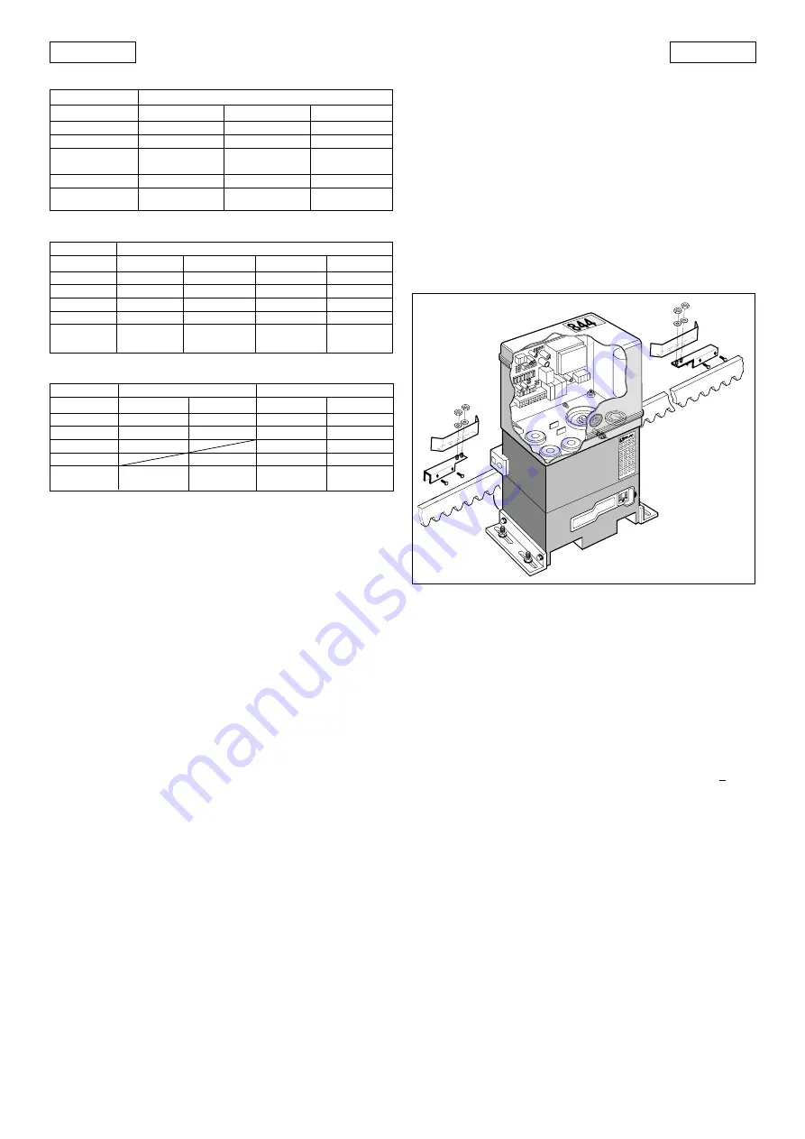
1)
Assemble the limit sensor centering the plate with respect to
the support threaded pins (Fig.26).
2)
Power up automation.
3)
Manually take the gate to opening position, leaving at least
2 cm from the travel limit mechanical stop.
4)
Allow the plate to slide over the rack in opening direction. As
soon as the FCA LED on the 844 T card goes off, move the plate
forward by about 45 mm and secure it to the rack by
tightening the screws.
5)
Manually take the gate to closing position, leave a distance
of about 2 cm from the travel limit stop mechanism.
6)
Allow the plate to slide over the rack in closing direction. As
soon as the FCC LED on the 844 T card goes off, move the
plate forward by about 45 mm and secure it to the rack by
tightening the screws.
7)
Re-lock the system (see paragraph 8).
8)
Command a complete gate cycle to check if the limit sensors
are tripping correctly.
N.B.: If the limit sensors are reversed (e.g. if the FCC LED goes
off when the gate is open), change over the cables con-
nected to the FCA and FCC inputs.
Notes on plate positioning
•
The distance between limit sensors and plates must be < 5mm
(Fig.11).
•
To avoid damaging the operator and/or interrupting opera-
tion, leave a distance of least 2 cm from the travel limit
mechanical stops.
5.7. ADJUSTING TRANSMITTED TORQUE
The 844 MC-T automation has an anti-crushing mechanical
clutch which (according to adjustment) limits the thrust of the
gate if it meets an obstacle.
After the obstacle is removed, the gate restarts moving either until
it reaches the limit sensor or when safety time has elapsed.
We advise you to set the torque limiter to conform to relevant
current laws.
Procedure for setting the tripping threshold of the anti-crushing
system:
1)
Turn off power to the automation.
2)
Remove the hole guard and fully unscrew the cover of the
clutch adjustment screw as shown in Fig.27.
(1) OPEN B input commands partial opening.
(2) With pre-flashing selected, movement begins after 5 sec.
(3) If the pulse is sent during pre-flashing, counting is restarted.
(4) OPEN B input commands closing.
(5) Push-button must be kept pressed to activate gate movement. When the
push-button is released, the gate stops.
5.4. FAULT CONDITIONS
The following conditions cause certain effects to normal operation
of automation:
a
microprocessor error
b
safety electronic timing tripped (operation is interrupted if
continuous work time exceeds 255 sec. ).
c
limit sensors disconnected (or both engaged)
• Conditions
a
and
b
cause automation to stop.
• Condition
c
causes an alarm situation disabling any activity:
Normal operation can be restored only after eliminating the
alarm cause and pressing the RESET push-button (or turning off
power supply momentarily).
To have this condition signalled, the warning light must be
connected: the alarm is signalled by very rapidly flashing light
(0.25 sec).
5.5. ROTATION DIRECTION CHECK
1)
Release the operator, take it manually to mid-travel and re-
lock it (see par. 8).
2)
Power up the system and then press the RESET push-button.
3)
Give an Open command to the operator, check if the gate
moves in opening direction and then press the RESET push-
button to stop the leaf moving.
4)
If rotation direction is incorrect, change over wiring of cables
T1 and T3 of the electric motor.
5.6. POSITIONING TRAVEL LIMIT PLATES
The 844 MT-C operator has inductive limit sensors (Fig.1 ref.3)
which, when they detect the movement of a plate secured to
the upper part of the rack, command gate movement to stop.
Procedure for correct positioning of the two supplied plates:
Fig. 26
TABLE 12
LOGIC C (DEADMAN)
TABLE 10
LOGIC E2 (SEMI-AUTOMATIC PLUS)
SAFETY DEVICES
no effect
no effect
stops and reverses
at disengagement (2)
no effect
no effect
GATE STATUS
CLOSED
OPEN
CLOSING
OPENING
STOPPED
OPEN A - OPEN B (1)
opens (2)
re-closes (2)
reverses motion
stops
re-closes (when safety devices
engaged, it re-opens) (2)
STOP
no effect
no effect
stops
stops
no effect
PULSES
LOGIC E2
TABLE 11
LOGIC B (SEMI-AUTOMATIC)
GATE STATUS
CLOSED
OPEN
CLOSING
OPENING
STOPPED
LOGIC B
PULSES
OPEN A
opens ( (2)
no effect
no effect
no effect
completes
opening (2)
OPEN B (4)
no effect
closes(2)
no effect
no effect
completes
closing (2)
STOP
no effect
no effect
stops movement
stops movement
no effect
SAFETY DEVICES
no effect
prevents closing
stops movement
no effect
prevents closing
GATE STATUS
CLOSED
OPEN
CLOSING
OPENING
STOPPED
LOGIC C
OPEN A (5)
opens
no effect
no effect
completes
opening
OPEN B (4 e 5)
no effect
closes
no effect
completes
closing
SAFETY DEVICES
no effect
prevents closing
stops movement
no effect
prevents
closing
STOP
no effect
no effect
stops movement
stops movement
no effect
CONTROLS HELD DOWN CONTINUOUSLY
PULSES