M
ODEL
SL900A V
ERSION
V_1.0
P
REPARED BY
H/W
D
ATE
2006.06.30
S
UBJECT
T
ECHNICAL
M
ANUAL
P
AGE
15/51
SL900A
T
ECHNICAL
M
ANUAL
Factory Programming
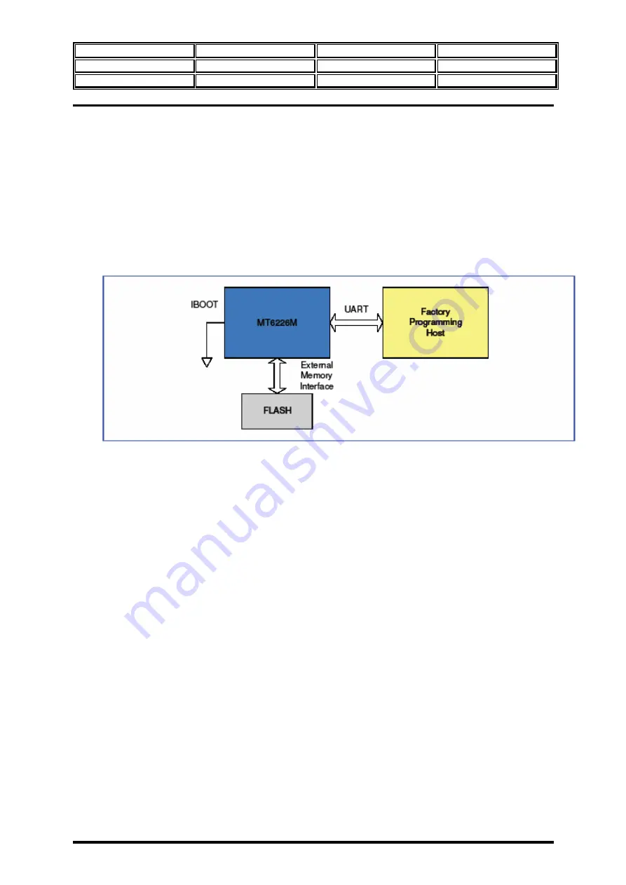
The configuration for factory programming is shown in Figure 8. Usually the factory programming host
connects with MT6226M via the UART interface. In order to have it work properly, the system should
boot up from Boot Code. That is, IBOOT should be tied to GND. The download speed can be up to 921K
bps while MCU is running at 26Mhz. After the system has reset, the Boot Code will guide the processor to
run the Factory Programming software placed in System ROM. Then, MT6226M will start and continue to
poll the UART1 port until valid information is detected. The first information received on the UART1 will
be used to configure the chip for factory programming. The Flash downloader program is then transferred
in to System RAM or external SRAM.
Figure 8. Factory Programming
3.3
Bus System
Two levels of bus hierarchy are employed in the Micro-Controller Unit Subsystem of MT6226M. As depicted
in Figure5, AHB Bus and APB Bus serve as system backbone and peripheral buses, while an APB bridge
connects these two buses. Both AHB and APB Buses operate at the same clock rate as processor core.
The APB Bridge is the only bus master residing on the APB Bus. All APB slaves are mapped onto memory
block MB8 in MCU 32bit addressing space. A central address decoder is implemented inside the bridge to
generate select signals for individual peripherals. In addition, since the base address of each APB slave has been
associated with select signals, the address bus on APB will contain only the value of offset address. The base
address and data width of each peripheral are listed in below table.
Содержание SL900A
Страница 1: ...SL900A SL900A ...


