


Set Amplifier Output Mode
Step 2 — Rear Panel Configuration
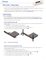
Follow the instructions below to learn how to configure the rear panel for the XPA U 3502.
•
Wire the source output to the Line Input 3.5mm captive screw port as shown below. Figure 3 shows both balanced and
unbalanced inputs.
ATTENTIONS:
•
Do not tie channel output pins to each other or to ground. Doing so will short out the outputs, damage the amplifier, or
both.
•
Ne pas lier les sorties 1 et 2 des canaux entre elles ou à la terre. Les sorties pourraient être court-circuitées et/ou
l’amplificateur pourrait être endommagé.
•
To avoid risk of damage to the amplifier or the speakers, only connect low-impedance speaker loads (8Ω/4Ω) to the
appropriately marked output connectors on the amplifier.
•
Pour éviter tout risque de détérioration de l’amplificateur ou des enceintes, connectez toujours les charges de l’enceinte
faible impédance (8Ω/4Ω) aux connecteurs de sortie correctement identifiés sur l’amplificateur.
NOTE:
You must use Class 2 wiring for the amplified outputs to comply with UL requirements.
" (5 mm) MAX.
3
16
Do not tin
the wires!
100-240V 1.5A, 50-60 Hz
2
0
2
4
6
8
10
14
18
26
∞
12
1
0
2
4
6
8
10
14
18
26
∞
12
1
2
G
G
C
V
G
C
V
ST
ANDB
Y
SIGNAL
1
SIGNAL
LIMITER/
PROTECT
LIMITER/
PROTECT
2
ATTENUATION
INPUTS
REMOTE
XPA U 3502
2
1
CLASS 2 WIRING
OUTPUTS
8Ω/4Ω
1
2
CH 2
Stereo 8Ω or 4Ω
Speaker Loads
Wire output connector
to speaker loads as
shown below
Wire CH 1 and CH 2
input connector based
on source as shown below
Use both CH 1 and CH 2
Attenuators (set
levels independently)
CH 1
Figure 3.
XPA 3502 Output Configuration
Step 3 — Remote Ports
STANDB
Y
1
G
V C
G
V C
G
2
REMOTE
Figure 4.
Remote Volume Control and Standby Ports
The 3.5 mm 5-pin captive screw remote control ports (shown above) are used to control volume on channel 1 on pins 1, 2, and 3,
and standby mode through contact closure on the pins 4 and 5. The upper, 3-pin captive screw remote control port is used to control
volume on channel 2.
The volume control ports can be wired to Extron remote volume controllers such as an Extron VCM 200 series and MLC 64 RS VC D
controllers, or Extron Control products with the digital Remote Volume Control Port, such as the MLC 100 Plus and IPCP Pro 255. For
more details on wiring the volume control ports see the
XPA U 3502 User Guide
.
XPA U 3502 • Setup Guide (Continued)
3


