XPA U 1004 SB and XPA U 2002 SB • Operation
13
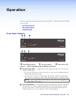
— (see
on page 12) Two rows of LEDs that
represent the amplifier’s channels.
•
Limiter/Protect LED
— The LEDs lights red when the channel is in protection
mode, which is triggered by any of the limiter protection circuits such as:
•
When the clip limiter is activiated due to excessive clipping.
•
When the output short circuits.
•
Signal LED
— The LEDs light green when the input signal is detected.
NOTE:
The LEDs are also located on the rear panel.
Rear Panel Features
BR
( )
100-240V --A, 50-60 Hz
3
4
1
2
CLASS 2 WIRING
0
2
4
6
8
10
∞
12
14
0
2
4
6
8
10
14
∞
12
2
4
3
0
2
4
6
8
10
14
18
26
∞
12
1
0
2
4
6
8
10
14
18
26
∞
12
1
2
3
4
G
G
C
V
G
C
V
ST
ANDBY
SIGNAL
1
SIGNAL
LIMITER/
PROTECT
LIMITER/
PROTECT
2
3 4
ATTENUATION
OUTPUT MODE
INPUTS
REMOTE
OUTPUTS
XPA U 1004 SB
BR
BR
BR
( )
1 & 2
1
BRIDGED
MONO
70V
70V (HPF OFF)
100V
STEREO
& 2
4Ω
8Ω
8Ω
16Ω
BRIDGED
MONO
70V
70V (HPF OFF)
100V
100V (HPF OFF)
100V (HPF OFF)
STEREO
4Ω
8Ω
8Ω
3&4
1&2
16Ω
100-240V --A, 50-60 Hz
1
2
CLASS 2 WIRING
0
2
4
6
8
10
14
∞
12
2
1
0
2
4
6
8
10
14
18
26
∞
12
1
2
G
G
C
V
STANDBY
SIGNAL
1
LIMITER/
PROTECT
2
ATTENUATION
OUTPUT MODE
INPUTS
REMOTE
OUTPUTS
XPA U 2002 SB
BR
BR
( )
1 & 2
BRIDGED
MONO
70V
70V (HPF OFF)
100V
100V (HPF OFF)
STEREO
4Ω
8Ω
8Ω
1&2
16Ω
A
B
D
E
G
F
C
A
B
D
E
G
F
C
A
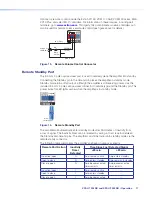
Removable IEC
Power Receptacle
B
Channel Status
LEDs
C
Attenuators
D
Output Mode
Selector Switches
Line Input
F
Speaker Output
Connectors
G
Remote Ports
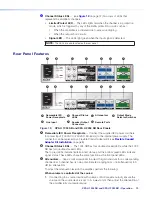
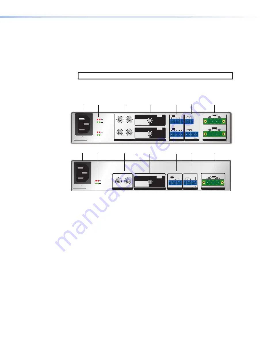
Figure 13.
XPA U 1004 SB and XPA U 2002 SB Rear Panels
A
Removable IEC Power Receptacle
— Connect the supplied IEC power cord here
for power input (100 VAC to 240 VAC, 50-60 Hz) to the internal power supply. The
connector can be replaced by a Flexible Conduit Adapter Kit (see
B
Channel Status LEDs
— The 1004 SB has four double-stacked LEDs, while the 2002
SB has two double-stacked LEDs.
The top red LEDs indicate limiter/protect status, and the bottom green LEDs indicate
signal status. These LEDs share the same function as the front panel LEDs.
C
Attenuators
— Use a small screwdriver to adjust the gain structure for a corresponding
channel. Each channel has its own potentiometer, ranging from ∞ (full attenuation) to 0
dB (no attenuation)
To adjust the attenuation level on the amplifier, perform the following:
When volume is controlled at the source:
1.
If connecting to a source device with volume control (variable output), ensure the
volume on the source device is set to its lowest point, then adjust the attenuation of
the amplifier fully counterclockwise.
Содержание XPA U 1004 SB
Страница 7: ......


