background image

XMP 240 C AT • Configuration Tools

76

3. 

Select 

Insert

. The action is inserted from the clipboard above the action that was right 

clicked in step 1.

To delete a macro action:

1. 

Right click the box furthest to the left in the action to be deleted.

2. 

Click 

Delete

.

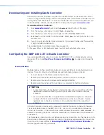
Device Manager

Device Manager

 is used to configure and switch between multiple devices in Live or 

Emulate mode within DSP Configurator (see 

Live and Emulate Panel

 on page 17). 

Devices can be placed and ordered in user-created folders for easily tracking systems with 
devices across multiple rooms. When 

Device Manager

 contains multiple devices, all device 

configurations are saved in a single DSP Configurator file.
Select 

Tools > Device Manager

 to open the 

Device Manager

 dialog box.

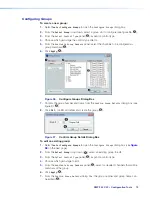
Figure 102. 

Device Manager Dialog Box

1  

Add Device Button

 — Click the 

 button to open the DSP Configurator splash 

screen to select another device to be configured. As a device is chosen or connected, it 
is added to the 

Device Manager

 dialog box.

2  

Clone Device Button

 —Click the 

 button to clone the currently selected device. 

When a device is cloned, information within the device configuration file is also cloned.

NOTE:

  If Live mode is enabled, a backup may need to be performed before the 

device can be successfully cloned.

3  

Remove Device Button

 — Click the 

 button to remove the currently selected 

device from the device manager. Select a folder and click this button to delete the folder 
and all devices it contains.

4  

Expand and Collapse All Buttons

 — Click the 

 icon to expand all folders and 

show the devices it contains. Click the 

 to collapse all folders.

5  

New Folder Button

 — Click the 

 button to create a new folder to drag a device into. 

1


Add Device Button

2


Clone Device Button

3


Remove Device Button

4


Expand and Collapse All Buttons

5


New Folder Button

6


Device List Panel

figure 57.   Device Manager Dialog Box

Содержание XMP 240 C AT

Страница 1: ...User Guide XMP 240 C AT Audio Products Mixers and Processors Expansion Matrix Processor 68 3434 01 Rev A 06 20 ...

Страница 2: ...oducto avisa al usuario de la presencia de importantes instrucciones de uso y mantenimiento recogidas en la documentación proporcionada con el equipo Para obtener información sobre directrices de seguridad cumplimiento de normativas compatibilidad electromagnética accesibilidad y temas relacionados consulte la Guía de cumplimiento de normativas y seguridad de Extron referencia 68 290 01 en el siti...

Страница 3: ...t PowerCage PURE3 Quantum ShareLink Show Me SoundField SpeedMount SpeedSwitch StudioStation System INTEGRATOR TeamWork TouchLink V Lock VideoLounge VN Matrix VoiceLift WallVault WindoWall XPA XTP XTP Systems and ZipClip Registered Service Mark SM S3 Service Support Solutions Trademarks AAP AFL Accu RATE Frame Lock ADSP Advanced Digital Sync Processing Auto Image AVEdge CableCover CDRS Class D Ripp...

Страница 4: ...es torsadées fonctionne avec les câbles paires torsadées blindées UTP ou non blindées STP Afin de s assurer de la compatibilité entre FCC Classe A et CE les câbles STP et les connecteurs STP sont nécessaires NOTES This unit was tested with shielded I O cables on the peripheral devices Shielded cables must be used to ensure compliance with FCC emissions limits For more information on safety guideli...

Страница 5: ...ples of computer or device responses used in this guide the character 0 is used for the number zero and O is the capital letter o Computer responses and directory paths that do not have variables are written in the font shown here Reply from 208 132 180 48 bytes 32 times 2ms TTL 32 C Program Files Extron Variables are written in slanted form as shown here ping xxx xxx xxx xxx t SOH R Data STX Comm...

Страница 6: ...enaming an Input 20 Inputs Overview 21 Input Building Blocks 22 Input Processing 23 Input Gain Block 24 Input Filter Block 25 Input AEC Block 27 Input Dynamics Blocks 30 Input Delay Block 35 Input Ducking Block 36 Input Automix Block 39 Input Pre Mixer Gain Block 40 Virtual Returns 41 Renaming a Virtual Return 42 Virtual Return Building Blocks 42 Virtual Return Processing 42 Virtual Return Feedbac...

Страница 7: ...ller Operation 98 Dante Transmitters and Receivers 98 Dante Routing Operation 98 Routing Devices 98 Disconnecting Inputs from Outputs 100 Sending SIS Commands to Dante Audio Interface Devices through the XMP 100 Dante Troubleshooting 101 Simplifying the Network for Troubleshooting 101 Troubleshooting the Network Interface 101 Restarting Dante Controller 102 Remote Communication and Control 103 Con...

Страница 8: ...Dante sources with enough outputs to support multiple zones and destination devices Ideal for network audio systems based on Dante or AES67 the XMP 240 allows for high channel count audio input and output processing Features 24 channels of AEC acoustic echo cancellation The XMP 240 includes 24 independent channels of high performance AEC as well as selectable noise cancellation Extron AEC features...

Страница 9: ...l yet user friendly PC based software tool for managing all audio operations of the XMP 240 It enables complete setup and configuration of digital audio processing tools on the ProDSP platform as well as routing and mixing Building Blocks for channel processor settings A collection of pre designed processor settings optimized for a specific type of input and output devices such as microphones and ...

Страница 10: ... AXI 44 AT CONFIG AXI 44 AT CONFIG AXI 44 AT CONFIG AXI 44 AT CONFIG Extron AXI 44 AT Dante Audio Interface Extron AXI 44 AT Dante Audio Interface Extron AXI 44 AT Dante Audio Interface Extron AXI 44 AT Dante Audio Interface Extron AXI 44 AT Dante Audio Interface Extron AXI 44 AT Dante Audio Interface Multi Purpose Room Table Mics Ceiling Array Mic 6 Speakers per Ch Zone Tapped 16W 6x16W 96 watts ...

Страница 11: ...cks so that uneven mechanical loading does not create a hazardous condition Circuit overloading When connecting the equipment to the supply circuit consider the effect that circuit overloading might have on overcurrent protection and supply wiring Consider equipment nameplate ratings when addressing this concern Reliable earthing grounding Maintain reliable grounding of rack mounted equipment Pay ...

Страница 12: ...0A MAX Rear Panel Power Receptacle Figure 3 Power Input Wiring ATTENTION Always use a power supply provided by or specified by Extron Use of an unauthorized power supply voids all regulatory compliance certification and may cause damage to the supply and the end product Utilisez toujours une source d alimentation fournie ou recommandée par Extron L utilisation d une source d alimentation non autor...

Страница 13: ... 0 per IEC TR62101 Le XMP est conçu pour une connexion à un circuit PoE pour une utilisation intérieure seulement et est considéré comme faisant partie d un environnement réseau 0 par IEC TR62101 B EXP Port One RJ 45 port allows two units to be connected via a shielded CAT 6 cable to form a larger matrix system 1 foot cable included Any Extron device with EXP capability can exchange audio with a X...

Страница 14: ...LEDs B USB Config Port D Input Indicator LEDs Figure 5 XMP 240 C AT Front Panel A Power LED Blinks during boot up and lights steadily when the XMP 240 C AT is operational B USB Config Port One USB mini B port is used for configuration This port can also be used for firmware updates C Activity Indicator LEDs These green activity LEDs indicate port activity on the XMP 240 C AT EXP Indicator LED On T...

Страница 15: ...ogram capability is enabled Sets IP addresses for LAN port back to factory default 192 168 254 254 Sets subnet masks for LAN port back to factory default 255 255 255 0 Sets gateways for LAN port back to factory default Turns DHCP off for LAN port If a second momentary press does not occur within 1 second Mode 4 is exited Mode 5 Factory Default Reset With power on press and hold the Reset button un...

Страница 16: ...sion Output Processing Virtual Returns Virtual Send Bus Virtual Return Processing Downloading and Installing DSP Configurator 1 From www extron com hover over the Download tab at the top of the page 2 From the Featured Software list select DSP Configurator Software 3 From the DSP Configurator Software product page click the blue Download button 4 Select Run to run the DSP Configurator installer Se...

Страница 17: ...gurator main workspace can be divided up into four main sections see figure 7 Each section contains various functions to configure the XMP 240 C AT Due to the large number of inputs and outputs available on the XMP 240 C AT not all channels can be viewed at the same time in a single window Use the expand and collapse buttons next to the input and output group names to show or hide input and output...

Страница 18: ...n As dialog box opens Enter a name and save location for the configuration file TIP It is best to create and save configuration files while in Emulate mode 4 Save As Saves the current configuration file under a new name and location or as a template file When selected the Save Configuration As dialog box opens 5 Export Single Device Saves the currently selected device in Device Manager as a config...

Страница 19: ...dow allowing use of the DSP Configurator workspace while simultaneously monitoring input and output activity NOTE The meter bridge is only available in Live mode with a TCP IP connection 2 Re enable All Dialogs This option re enables all dialog boxes that no longer appear based on user selection certain dialog boxes that appear are user defeatable by selecting a checkbox that reads Do Not Show Thi...

Страница 20: ...e Manager dialog box Device Manager on page 76 6 Issue RESET Command Clears the XMP 240 of all processors and other configuration settings This command does not reset general settings such as IP address 7 Firmware Loader Opens the Firmware Loader application if it is installed Firmware Loader on page 79 Visit www extron com to download the software 8 Organize Building Blocks Opens the Organize Bui...

Страница 21: ...s a list of all open windows Select a window from the list to bring it into focus and to the forefront of the workspace Windows appear in the order they were opened Help Figure 13 Help Menu 1 Contents Opens the DSP Configurator Help file where detailed information about DSP Configurator can be found 2 Search Opens the DSP Configurator Help file with the Search field in focus 3 About Opens a window...

Страница 22: ...ration file or on a device connected in Live mode Presets with an asterisk next to them are on the XMP 240 C AT but not in the current configuration file Run a preset to load it into the configuration file Alternatively perform a backup to run all presets and load them into the current configuration file File on page 12 Figure 15 Presets Drop Down Menu After selecting a preset from the list choose...

Страница 23: ...u options or actions are available in Emulate mode Live Mode Enter Live mode to connect to a XMP 240 C AT and push or pull configurations between the device and host PC In Live mode changes made in DSP Configurator are directly applied to the XMP 240 C AT Additionally presets and macros can be created and stored on the device When entering Live mode the user is prompted with the Connect to device ...

Страница 24: ... configurations from the device and displays it in the DSP Configurator main workspace b Push Pushes the configuration file presets macros and ACP configurations open in DSP Configurator to the connected XMP 240 The check boxes indicate what will be pushed when OK is selected Pushing a selected item will overwrite that item on the device NOTE If only pushing selected presets the preset selection d...

Страница 25: ...urrent state of the connected XMP 240 C AT is displayed in the DSP Configurator status panel and the device is ready for further configuration Exit Live Mode and Enter Emulate Mode 1 Click the Emulate button in the DSP Configurator menu bar see figure 23 1 Alternatively select Tools Disconnect from Device or press F6 on the keyboard Figure 23 Emulate Button 2 Click OK to confirm Figure 24 Confirm ...

Страница 26: ...annels on the XMP 240 are shown in DSP Configurator under the Inputs panel Figure 25 Inputs Inputs 1 24 offer AEC Acoustic Echo Cancellation DSP capability Inputs 25 48 do not have AEC The 48 channels of Dante inputs and 16 channels of audio via the EXP port are available as digital sources for the XMP 240 inputs Renaming an Input NOTE Renaming an AT input in DSP Configurator affects the receiver ...

Страница 27: ...name field Figure 28 Renamed Input Inputs Overview With the Extron Expansion Port EXP two EXP enabled devices can be connected for bidirectional communication When two units are connected one unit must be set as the Primary Unit and the other must be set as the Secondary Unit see Expansion Bus on page 88 This synchronizes the sampling clocks of the two units AT inputs allow a XMP 240 C AT model to...

Страница 28: ...pen the Building Blocks dialog box 1 Building Block Folders 4 Delete a Building Block Button 2 General Building Blocks 5 New Folder Button 3 Add a Building Block Button 6 Building Blocks Help Button Figure 31 Input Building Blocks Dialog Box 1 Building Block Folders These folders group input types together such as table or handheld mics for easy access see figure 32 Figure 32 Mic Building Block Fo...

Страница 29: ...ew folder or sub folder in the Building Blocks dialog box 6 Building Blocks Help Button Opens the Building Blocks topic of the DSP Configurator Help file This topic contains more information on the different types of building blocks for inputs and outputs Input Processing The input processing chain in DSP Configurator is visually represented by a string of blocks see figure 34 Each block contains ...

Страница 30: ... box Options on page 87 the clip box located at the top of the meter lights red 4 dBFS Numeric Readout This read only text box displays the numerical value of the input signal level in dBFS 5 Input Gain Text Field This text field allows the user to enter a gain or attenuation value in 0 1 dB steps 6 Polarity Toggle Button Inverts the signal polarity of the selected input When the button displays t...

Страница 31: ...of the eleven available filters to insert into the block Figure 38 Filter Block and Drop Down Menu Alternatively right click the Filter block and select Insert then select a filter to insert it into the block Figure 39 Insert Filter Drop Down Menu Once an initial filter is selected the Filter block changes to display the type of filter applied For example if High Pass Filter is selected the Filter...

Страница 32: ...the center frequency of the filter If a filter is active unbypassed it appears as a solid red curve If a filter is bypassed it appears as a broken orange curve such as the bass filter in slot 2 NOTE All filters are bypassed by default 3 Filter List Provides filter drop down menus for all 5 available filter slots Frequency Slope Boost Cut Q and Bypass controls are also available in this list Availa...

Страница 33: ...the far end The amount of signal sent back to the far end talker can be substantial and with the added transmission delay the result is an echo effect that can seriously compromise communication in a teleconference or videoconference The Extron Acoustic Echo Cancellation AEC processor removes the potential echo signal at the near end mic channel by comparing it to the received signal from the far ...

Страница 34: ...el Figure 44 AEC Dialog Box 1 Activity Panel Far lights when signal activity is detected from the far end Near lights when activity is detected from the near end Update lights when AEC is updating converging or reconverging 2 ERL Meter ERL echo return loss is the ratio of the far end signal at the reference input to the far end signal received at the mic input and is expressed in dB This meter sho...
Страница 35: ...EC Advanced Options below AEC Help Button Opens the Acoustic Echo Cancellation topic of the DSP Configurator Help file for further assistance in operating AEC processor AEC Advanced Options The AEC dialog box provides advanced NLP non linear processing options for fine tuning echo cancellation These options are hidden by default Click the Show Hide Advanced Options button to access them see figure...

Страница 36: ...wn Menu From the Dynamics drop down menu four types of dynamics processors are available Select a dynamics processor type to insert it into the Dynamics block There are two Dynamics blocks available per mic line input channel Each block can be configured with any of the processor types The four types of dynamics processors available are AGC Automatic Gain Control on the next page Compressor on pag...

Страница 37: ...e and use the Left Arrow and Right Arrow keys to adjust the respective parameter in 1 ms steps 4 Bypass Button Bypasses the AGC processor When the button is red bypass is enabled 5 Set Defaults Button Resets all AGC parameters to their default values To view individual parameter default values see the DSP Configurator Help file by clicking the Dynamics Help button 8 and opening the About Dynamics ...

Страница 38: ...elect the Soft Knee checkbox to provide a more natural implementation of compression when the signal reaches the threshold 4 Bypass Button Bypasses the compressor When the button is red bypass is enabled 5 Set Defaults Button Resets all compressor parameters to their default values To view individual parameter default values see the DSP Configurator Help file by clicking the Dynamics Help button 8...

Страница 39: ...mplementation of limiting when the signal reaches the threshold 4 Bypass Button Bypasses the limiter When the button is red bypass is enabled 5 Set Defaults Button Resets all limiter parameters to their default values To view individual parameter default values see the DSP Configurator Help file by clicking the Dynamics Help button 8 and navigate to the About Dynamics topic 6 OK Button Confirms ch...

Страница 40: ...ow and Right Arrow keys to adjust the respective parameter in 1 ms steps 4 Bypass Button Bypasses the noise gate When the button is red bypass is enabled 5 Set Defaults Button Resets all noise gate parameters to their default values To view individual parameter default settings see the DSP Configurator Help file by clicking the Dynamics Help button 8 and navigate to the About Dynamics topic 6 OK B...

Страница 41: ...and use the Up Arrow or Down Arrow to adjust delay in 1 sample steps or the 1 sample equivalent in milliseconds feet or meters Use the text box below the fader to input a delay value 4 Temperature Panel Becomes available when using delay in feet or meters Compensates delay for ambient temperature in the acoustic space Temperature is not available when using samples or milliseconds as the unit of m...

Страница 42: ...e Duck block to open the drop down menu where the Ducker and Adaptive Gain processors can be selected Figure 55 Duck Block and Drop Down Menu Select Ducker to insert a ducking processor into the duck block Select Adaptive Gain to insert an adaptive gain processor into the duck block Depending on the processor selected the duck block displays DUCK for a ducker or AG for adaptive gain Figure 56 Duck...

Страница 43: ...ings Contains controls for setting Threshold Attack Time Hold Time and Release Click the Ducking Operation Help button 4 to open the Ducking Operation topic in the DSP Configurator Help fie 3 Duck Priority Tree Displays the ducking priority for all Input and Aux In channels Select another input to populate the Ducker Configuration dialog with the ducker information for that channel Channels with a...

Страница 44: ... to that channel when signal exceeds the threshold on the adaptive gain trigger channel NOTE For every 1 dB of signal beyond the level set in the Threshold field 1 dB of gain will be added to the channels selected in the Add Gain To column This occurs until the maximum gain set in the Max Gain dB field has been applied 2 Adaptive Gain Parameter Settings Contains controls for Threshold Attack Time ...

Страница 45: ...ton for more information regarding Automix Groups 4 Automix Parameters Provides configuration controls for all automix parameters 5 dBFS Meter Displays the post automix signal level 6 Gate Status Indicator This LED lights when monitoring is enabled and the gate is open 7 Monitor Gate Checkbox Click the Monitor Gate checkbox to enable SIS responses regarding gate status see Automixer Gate Monitorin...

Страница 46: ... signal level immediately after the status has changed see Automixer Gate Monitoring on page 125 for SIS response syntax Comparing the automixer gate threshold setting to the gate status in the response will indicate whether the automixer gate has opened or closed When the gate status in the response is 1024 or greater the gate has opened and when the gate status in the response is less than 1024 ...

Страница 47: ...ox 6 Cancel Button Reverts any changes made to the contained parameters back to their states when the current instance of the Pre mixer Gain dialog box was opened and closes the dialog box 7 Pre mixer Gain Help Button Opens the Pre mixer Gain topic of the DSP Configurator Help file for further assistance in understanding operating the Pre mixer Gain dialog Virtual Returns Virtual returns receive s...

Страница 48: ...16 virtual return channels see Input Building Blocks on page 22 for more information on configuring virtual return building blocks Virtual Return Processing Virtual returns A through H contain the following signal processing chain 1 Virtual Return Feedback Suppressor Block 2 Virtual Return Filter Block 3 Virtual Return Dynamics Block 4 Virtual Return Delay Block 5 Virtual Return Pre Mixer Gain Blo...

Страница 49: ...ously detected frequency up to 5 dynamic filters can be transferred into fixed filters Once a dynamic filter is transferred into a fixed filter it can only be overwritten by manually assigning a new frequency to the filter Double click the feedback suppressor block to show the feedback suppressor drop down menu Select Feedback Suppressor to insert a feedback suppressor processor into the signal ch...

Страница 50: ...kbox that enables the Hold Time parameter Entering a time into the Hold Time text boxes sets how long each dynamic filter will hold before removing the filter 7 Bypass FBS Turns off feedback detection when bypass is engaged button is red when bypass is engaged Only the dynamic filters are bypassed Fixed filters remain active 8 Set Defaults Button Resets parameters on all tabs to their default valu...

Страница 51: ... and contained parameters 5 Clear All Button Clears all dynamic filters and resets the feedback detection and suppression process 6 Lock Button Locks current dynamic filters and prevents more dynamic filters from being applied 7 Bypass FBS Button Bypasses the FBS processor When the button is red FBS is bypassed 8 Set Defaults Button Resets parameters on all tabs to their default values and positio...

Страница 52: ...the button is red FBS is bypassed 7 Set Defaults Button Resets parameters on all tabs to their default values and positions 8 OK Button Confirms changes made to the contained parameters and closes the Feedback Suppressor dialog box 9 Cancel Button Reverts any changes made to the contained parameters back to their states when the current instance of the Feedback Suppressor dialog box was opened and...

Страница 53: ...k see Input Delay Block on page 35 for information on configuring the virtual return delay block Virtual Return Pre Mixer Gain Block The virtual return pre mixer gain block functions the same as the mic line input pre mixer gain block see Input Pre Mixer Gain Block on page 40 for information on configuring the virtual return pre mixer gain block Mix Points DSP Configurator contains twelve mix matr...

Страница 54: ...XMP 240 C AT DSP Configurator Software 48 Figure 72 DSP Configurator Mix Matrices Part 1 1 Inputs to AT Outputs 2 Inputs to Virtual Sends ...

Страница 55: ...s 3 Level Text Box Allows specific level values to be entered in 0 1 dB steps 4 Mute Button Mutes the mix point muted by default When the button is red the mix point is muted 5 Mix Dot Selection Three radio buttons provide options to choose the type of input processing applied to the mix point NOTE Mix dot selections are not available on Virtual Returns 6 OK Button Confirms changes made to the con...

Страница 56: ...the mix point parameter configuration preparing it to be pasted to another mix point The parameter configuration information is not removed until it is pasted to another mix point 7 Copy Copies the mix point parameter configuration leaving the mix point intact and preparing it to be pasted to another mix point 8 Paste Pastes a previously cut or copied mix point parameter configuration to the selec...

Страница 57: ...rom the field to confirm and apply the new output name Press the Down Arrow key to navigate to and highlight the next name field Figure 79 Renamed Output NOTE Follow the same procedure to edit an Output name Output Building Blocks Extron building blocks are a quick configuration tool that can significantly reduce configuration time A building block is a collection of processor and gain settings fo...

Страница 58: ...lder to save the block to an existing folder or create a new folder Figure 82 Add a Building Block Dialog Box 3 Delete a Building Block Button Deletes the currently selected building block or building block folder If default building blocks are deleted they can be restored from the Organize Building Blocks dialog box 4 New Folder Button Creates a new folder or sub folder 5 Building Blocks Help But...
Страница 59: ...cted output Figure 85 Post mixer Trim Dialog Box 1 Output Name This name changes to match the default or user defined output name 2 Post mixer Trim Fader Click and drag the trim fader to provide up to 12 dB of gain or 12 dB of attenuation in 0 1 dB steps Click the trim fader and use the Up Arrow or Down Arrow to adjust the fader up or down in 0 1 dB steps 3 Post mixer Trim Text Box Allows the user...

Страница 60: ...ion on configuring the output dynamics block Output Attenuation Block Double click the output Attenuation block to open the Attenuation dialog box Figure 86 Output Attenuation Block The Attenuation dialog box provides attenuation control for the selected output Figure 87 Attenuation Dialog Box 1 Output Name This name changes to match the default or user defined output name 2 Output Attenuation Fad...

Страница 61: ...verts any changes made to the contained parameters back to their states when the current instance of the Attenuation dialog box was opened and closes the dialog box Virtual Send Bus The virtual send bus consists of mix points that allow inputs to be routed back to the virtual return input panel for additional mixing and processing see Virtual Returns on page 41 NOTE Virtual Send Bus mix points are...

Страница 62: ...ls menu Figure 90 Presets Options 1 Mark All Items Marks all gain blocks processor blocks and mix points in the main workspace Performing this function before saving a preset ensures every element in the workspace is saved to the preset 2 Save Preset Saves the marked blocks and mix points of the current configuration as a preset When Save Preset is clicked the following dialog box opens saying tha...

Страница 63: ...s Ctrl Click to mark additional items anywhere in the main workspace Figure 92 Marked Items Highlighted in Green Configuring Presets 1 Create a configuration to be saved as a preset see DSP Configurator Software on page 10 2 Mark the items that will be included in the preset 3 Select Tools Presets Save Preset 4 From the Save a Preset dialog box enter the preset number 1 through 32 in the Preset Nu...

Страница 64: ...reble lists NOTE Bass and Treble are only available if the Bass and Treble filters are inserted on a channel and only allow channels with the filters to be placed in a group 3 Available Group Members This section populates according to the selected control type and lists all inputs mix points and outputs available to be added as group members Check the box next to a member to add it to the group G...

Страница 65: ... Confirm the group number and name from the Confirm Group Details dialog box see figure 97 5 8 Click OK to confirm all details and create the group 6 Figure 97 Confirm Group Details Dialog Box To edit an existing group 1 Select Tools Configure Groups to open the Configure Groups dialog box see figure 98 on the next page 2 From the Select Group drop down 1 select an existing group to edit 3 From th...

Страница 66: ...ox opens click OK to confirm the changes made to the group To edit only a group name or group number 1 Choose the group from the Select Group drop down 1 2 Click Change Name 7 3 From the Change Group Name dialog box enter the new group number or group name into the respective fields 5 4 Click OK 6 Figure 98 Editing a Group ...

Страница 67: ...rrently selected macro to a new macro slot 6 Run Macro Button Runs the macro currently selected from Select Macro drop down performing all of the configured actions in sequential order This is only available when connected to a XMP 240 C AT in Live mode via the LAN port 7 Edit Remote Destinations Button Opens the dialog box to edit data for remote devices being configured by the actions in a macro...

Страница 68: ...gain block on a specific channel Meters On Off Enable or disable level meters at the input gain or output attenuation stages of a specific channel SIS Command Type in a single SIS command to perform an action not listed above see Remote Communication and Control on page 103 NOTE Use the W key in place of E and the pipe key in place of Set Input Format Specify whether mic line inputs receive analog...

Страница 69: ...figuration data is deleted To delete a Macro 1 Click Tools Configure Macros 2 From the Select Macro drop down choose the macro to be deleted 3 Once the macro information is displayed click Delete Current Macro in the bottom left corner of the Configure Macros dialog box To clone a Macro 1 Click Tools Configure Macros 2 From the Select Macro drop down choose the macro to be cloned 3 Click Clone Mac...

Страница 70: ...Right click the left most box in the action line item see figure 99 3 on page 78 and select an option from the drop down menu Figure 101 Macro Action Manipulation Drop Down To cut a macro action 1 Right click the box furthest to the left in the action list item to be cut 2 Select Cut The action is removed from the list and placed in the clipboard To copy a macro action 1 Right click the box furthe...

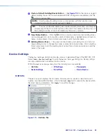
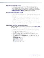
Страница 71: ...e button to open the DSP Configurator splash screen to select another device to be configured As a device is chosen or connected it is added to the Device Manager dialog box 2 Clone Device Button Click the button to clone the currently selected device When a device is cloned information within the device configuration file is also cloned NOTE If Live mode is enabled a backup may need to be perform...

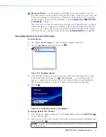
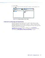
Страница 72: ...on Bus on page 88 Managing Devices in Device Manager To add a device 1 Click Tools Device Manager to open the Device Manager dialog box 2 Click the Add Device button see figure 103 1 Figure 103 Adding a Device 3 From the DSP Configurator splash screen drop down select the device to be added to Device Manager see figure 104 2 Select Connect to open the Connect to device dialog box and directly conn...

Страница 73: ...ds Connect to Device and opens the Connect to device dialog box when selected When DSP Configurator is in Live mode and connected to a device this selection reads Disconnect from Device and disconnects DSP Configurator from the current device when selected and returns to Emulate mode For detailed instructions on connecting to a XMP 240 C AT see Connect to a XMP 240 C AT in Live Mode on page 17 For...

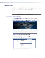
Страница 74: ...st be installed on the host PC in order for it to be opened TCP IP connection is recommended for updating firmware Downloading Firmware Updates 1 Go to www extron com and click the Download tab at the top of the page see figure 106 1 2 From the Download page select the Firmware link 2 near the middle of the page Figure 106 Download Page and Firmware Link 3 The Firmware link opens the firmware Down...

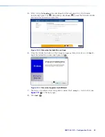
Страница 75: ... installer and install the firmware at a later time Figure 108 Firmware Installer Run or Save 6 Once the installer has been run the Firmware Upgrade dialog box opens click Next to begin the installation process see figure 109 6 Figure 109 Firmware Upgrade InstallShield 7 The terms of installation must be agreed to Select the I accept radio button see figure 110 7 on the next page 8 Click Next 8 ...

Страница 76: ...irmware Upgrade dialog box displays that the installation is complete and the install location of the firmware file By default firmware is installed in Program Files Extron Firmware XMP_240 vx xx If the View Firmware Release Notes checkbox is checked see figure 111 9 a PDF of the firmware release notes opens automatically The box is checked by default Click Finish to close the dialog box Figure 11...

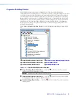
Страница 77: ...ng blocks in the Organize Building Blocks dialog are organized into folders for easily locating building blocks for a multitude of applications Select Tools Organize Building Blocks to open the Organize Building Blocks dialog box 1 Export Building Blocks File Button 4 Restore Default Building Blocks Button 2 Import Building Blocks File Button 5 New Folder Button 3 Delete Building Block Button 6 Bu...

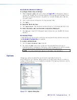
Страница 78: ...d Click a folder name twice to edit the folder name 6 Building Blocks Panel This panel contains folders and building blocks Click and drag building blocks to change their order or place them inside folders Click a building block name twice to edit the building block name Click a folder name twice to edit the name of the folder Device Settings The Device Settings dialog box provides access to gener...

Страница 79: ...ese settings apply to the port marked LAN Figure 114 IP Settings Tab Passwords The Passwords tab allows the user to create or edit user and administrator passwords An administrator password must be created in order to create a user password The checkbox to the left of the password type Admin or User must be checked before creating or editing passwords Click Apply to save the changes NOTES Password...

Страница 80: ...et the date and time 1 Click the Set Local button to sync the date and time information with the date and time on the connected PC 2 Set the time zone by using the Zone drop down 3 Use the Daylight Savings radio buttons to enter the daylight saving region or leave off default or 1 Click on the Set Date and Time check box 2 Enter the desired date in the Date field A drop down calendar is available ...

Страница 81: ...ely after it is connected to the Dante network and before audio connections with other devices are established Existing connections are removed when a device is renamed Il est essentiel d identifier un appareil Dante immédiatement après sa connexion au réseau Dante et avant tout établissement de connexion audio avec d autres appareils Les connexions existantes sont supprimées dès qu un appareil es...

Страница 82: ...h information from the XMP 240 Dante interface Redundant Mode In redundant mode the 2 port AT switch becomes separate Primary and Secondary ports see Redundant Configuration on page 96 To enable redundant mode 1 Click the Enable Redundant Mode checkbox 2 By default the DHCP radio button is selected to have the DHCP server assign a redundant network configuration If necessary select the Static radi...

Страница 83: ... an XMP 240 C AT Device and an EXP enabled non AT Device 1 Connect Live to the XMP 240 C AT 2 Double click on a DIG GAIN block see Input Gain Block on page 24 The Input Gain dialog box opens 3 From the Source drop down list select the desired source see Input Gain Block on page 24 4 Connect Live to the DMP 128 Plus non AT If connecting a DTP CrossPoint proceed to step 6 5 Select Tools Expansion Bu...

Страница 84: ...nte Controller software application is used to route audio on the network Dante allows audio channels to be transported across a switched Ethernet data network while meeting the quality requirements of professional audio Up to 48 channels can be transmitted from the XMP 240 C AT to the Dante network and up to 48 channels can be received by the XMP 240 C AT from the Dante network Audio signals are ...

Страница 85: ...he same Dante network can present difficulty in identifying individual devices To avoid confusion and difficulty ensure the following steps are taken Connect devices to the Dante network one at a time Rename each device before making audio connections in Dante Controller Rename each device with a unique and meaningful identifier Rename each device before the next device is connected to the Dante n...

Страница 86: ...ls can be up to 31 characters in length Label names are not case sensitive For example ANALOG OUT 1 and analog out 1 are recognized as the same name Unicode and non roman characters are not supported Tx and Rx channel labels can use any character except equals period or Tx and Rx channel labels must be unique on a device but do not need to be unique on the network Renaming the XMP 240 C AT in Dant...

Страница 87: ...ddresses listed on the rear panel of a XMP 240 C AT one for the LAN port and one for the Dante interface The Dante interface MAC address is listed beneath the LAN port MAC address The Device View dialog populates with the selected XMP 240 C AT information Figure 123 Populated Device View Dialog Box 6 Click the Device Config tab see figure 124 1 to open the Device Config page 7 In the Rename Device...

Страница 88: ...troller To better organize the various receivers and transmitters it is recommended each receiver and each transmitter be named using a description of the device they belong to the location of the device or the purpose of the receiver or transmitter To view the receiver or transmitter channels in Dante Controller click the sign next to the receiver or transmitter device name to expand it The sign ...

Страница 89: ...naming receivers close the Device View dialog box Figure 127 Device View Screen Renaming a Receiver Renaming a Transmitter The default names shown in the Dante Transmitters column are extracted from the Dante interface of the connected device see figure 126 2 on the previous page The XMP 240 transmitters are labelled Exp_Out 01 through Exp_Out 48 Follow the instructions on the next page to rename ...

Страница 90: ...ult name consists of the product name followed by a hyphen plus the last 6 digits of the device MAC address for example XMP240CAT 0ee8ee 1 Open Dante Controller 2 On the Dante Controller Network View screen click the Device Info tab see figure 129 1 3 On the Device Info page locate the name of the XMP 240 C AT in the Device Name column 2 The IP address is located in the Primary Address column 3 In...

Страница 91: ...MP EXP AT REMOTE R LAN 1 PRI PoE 2 SEC RS 232 Tx Rx G POWER 12V 1 0A MAX XMP 240 C AT Ethernet Figure 130 Daisy Chain Network Topology NOTE The daisy chain topology only functions in switched mode It is not possible to use it in redundant mode Redundant Configuration In redundant mode the 2 port AT switch becomes two separate primary and secondary ports that duplicate audio traffic Port 1 is marke...

Страница 92: ...ndant 3 Figure 132 Redundant Mode Configuration in Dante Controller To configure the XMP 240 C AT in redundant mode using DSP Configurator 1 Use DSP Configurator to connect to the XMP 240 C AT in Live mode see Live and Emulate Panel on page 17 2 Select Tools Device Settings 3 In the Device Settings dialog box use the right navigation arrow to navigate to and select the Dante Device tab see figure ...

Страница 93: ...lable in Dante Controller for routing to other Dante devices see Dante Transmitters and Receivers above Routing Devices After the XMP 240 C AT is configured the channels can be routed to the other Dante devices on the audio network Channels transmitted to the network or received from the network are routed using the Dante Controller Routing tab on the Network View page see figure 134 on the next p...

Страница 94: ...rs of a Dante device click the box next to the desired device in the Dante Transmitters panel such as AXI22D ConfRm1 see figure 134 1 The changes to a sign when the device expands 4 To show the receivers of a Dante device click the box next to the desired device in the Dante Receivers panel such as XMP240CAT MainRack 2 5 Click the intersection of the desired subscription between a transmitter and ...

Страница 95: ...ee Remote Communication and Control on page 103 3 Use the Set verbose mode command to set the XMP 240 to Verbose mode 3 see Set verbose mode on page 112 Example Command Response w3cv Vrb3 4 Use the Query available remote devices command see Query available remote devices on page 120 to receive a list of Dante devices that are currently connected to the XMP Example Command Response waexpr ExprA AXI...

Страница 96: ...e network and restart Dante Controller This can be enough for the software to reacquire the Dante network If the problem persists perform the following troubleshooting procedures in the order listed Simplifying the Network for Troubleshooting If further troubleshooting of Dante Controller is necessary begin by simplifying the network 1 Bypass network switches by connecting two Dante compatible uni...

Страница 97: ...l software on the computer 4 Enable DHCP on the remaining network connection This forces the computer to acquire an IP address from the Dante interface NOTE A DHCP server must be on the network for DHCP to function correctly Restarting Dante Controller If subscriptions or normal operation cannot be restored restart Dante Controller software To access the Dante Controller Help file do any of the fo...

Страница 98: ...omputer or other device such as a control system attached to the rear panel RS 232 port or LAN port or the front panel USB Config port The XMP 240 C AT can be set up and controlled using SIS commands or DSP Configurator software see Installation on page 4 for pin assignments and details on the configuration and control port connections For information on DSP Configurator see DSP Configurator Softw...

Страница 99: ...avior the product exhibits when communicating by serial port or USB The XMP 240 C AT LAN 1 port defaults are as follows IP Address Subnet Mask Default Gateway DHCP 192 168 254 254 255 255 255 0 0 0 0 0 OFF The Ethernet cable can be terminated as a straight through cable or a crossover cable and must be properly terminated for your application Crossover cable Direct connection between the computer ...

Страница 100: ...nection active If there are long idle periods disconnect the socket and reopen the connection when another command must be sent USB Config Port The XMP 240 C AT has a front panel USB port that can be connected to a computer as a host device running DataViewer utilities for control of the device Once a connection is established SIS programming can begin see Host to Device Communications on the next...

Страница 101: ...nn nn Day DD MMM YYYY HH MM SS Vn nn is the firmware version number 60 nnnn nn is the XMP 240 C AT part number The XMP 240 C AT sends the boot and copyright messages under the following circumstances If the XMP 240 C AT is off and RS 232 connection is already set up the PC is cabled to the XMP 240 C AT and a serial communication program such as DataViewer is open the connected unit sends these mes...

Страница 102: ...se tables list valid ASCII commands the XMP 240 C AT responses to the host and descriptions of the command functions with the results of executing the commands Symbol Definitions Carriage return with line feed Carriage return no line feed Space character Pipe can be used interchangeably with the character E Escape key W Can be used interchangeably with the E character NOTES Only instances marked w...

Страница 103: ...ivilege violation E13 Invalid parameter E25 Device not present E14 Not valid for this configuration E26 Maximum number of connections exceeded E17 Invalid command for signal type E27 Invalid event number E18 System command timed out E28 Bad filename or file not found Simple Control Port Commands Upper and lower case text can be used interchangeably except where noted Port 23 is the default port fo...

Страница 104: ...irmware Version w build Q version x xx xxxx Verbose mode 2 3 Bld version x xx xxxx Query Firmware Version Advanced X4 Q Specific Version Info see X4 list Verbose mode 2 3 Ver X56 Specific Version Info Query Part Number N zz zzzz zz Verbose mode 2 3 Pno zz zzzz zz KEY X4 Firmware Query 0 Detailed version information includes all 2Q 3Q and 4Q 1 Firmware version 2 Final stage bootloader 3 Factory bas...

Страница 105: ... Cpn1 CcpX2 X2 X2 X2 View parameters E1CP X2 X2 X2 X2 View mode E1CY X2 Configure flow control E1 X3 X3 CF Cpn1 CflX3 X3 View flow control E1CF X3 X3 KEY X1 General Information Query X2 Baud rate 300 600 1200 1800 2400 3600 4800 7200 9600 14400 19200 28800 38400 57600 115200 default 9600 X2 Parity Odd Even None Mark Space Only use the first letter default N None X2 Data bits 7 8 default 8 X2 Stop ...

Страница 106: ...X33 View subnet mask ECS X33 Set gateway IP address EX1 CG Ipg X1 View gateway IP address ECG X1 KEY X Greenwich Mean Time GMT offset value 12 00 to 14 00 This represent hours and minutes hh mm offset from GMT X1 Unit name is a text string up to 63 characters 24 before 2 2013 drawn from the alphabet A Z digits 0 9 minus sign hyphen X1 Set local date and time format MM DD YY HH MM SS X1 IP address ...

Страница 107: ... X57 X1 CISG Cisg X57 X1 X57 X1 View IP subnet gateway EX57 CISG X1 X57 X1 Set DNS server IP address EX1 DI Ipd X1 View DNS server IP address EDI X1 Set verbose mode EX2 CV VrbX2 View Verbose mode ECV X2 Get connection listing ECC number of connections Verbose modes 2 3 Icc number of connections KEY X1 IP Address xxx xxx xxx xxx Leading zeros in each of the 4 fields are optional in setting values ...

Страница 108: ...if not instead of actual password X5 Connection s security level 11 user 12 administrator NOTE The factory configured password for this device has been set to the device serial number Passwords are case sensitive Directories Change Create directory Epath directory CJ Dir path directory Back to root directory E CJ Dir Up one directory E CJ Dir path directory View current directory ECJ path director...

Страница 109: ...e XF Cfg1 config type Restore device configuration E0 config type XF Cfg0 config type NTP Network Time Protocol Enable NTP to set the time E1NTEN Nten1 Disable NTP E0NTEN Nten0 Sync NTP now E2NTEN Nten2 View NTP status ENTEN X3 Set NTP IP address EX1 NTIP NtipX1 Reset NTP IP address E NTIP Ntip Sets address to default View NTP IP address ENTIP X1 Set NTP port map EN port PMAP PmapN port Reset NTP ...

Страница 110: ... EA161PMAP PmapA00161 Disable SNMP port EA0PMAP PmapA00000 View SNMP port map EAPMAP port Set SSH port map EB port PMAP PmapB port Reset SSH port map EB22023PMAP PmapB22023 Disable SSH port EB0PMAP PmapB00000 View SSH port map EBPMAP port Set SSL port map ES port PMAP PmapS port Reset SSL port map ES443PMAP PmapS00443 Disable SSL port ES0PMAP PmapS00000 View SSL port map ESPMAP port Set FTP port m...

Страница 111: ... Not Specified View unit location ELSNMP X58 Set community public read only EPX58 SNMP SnmpP X58 Set community public to default EP SNMP SnmpP public View community public EPSNMP X58 Set community private read write EXX58 SNMP SnmpX X58 Set community private to default EXSNMP X58 SnmpX private View community private EXSNMP X58 Enable SNMP access and traps EE1SNMP SnmpE 1 Disable SNMP access and tr...

Страница 112: ... Standard Host control Default SIS 2 Disable Port Ping Execute test E address name PING address bytes ttl time Verbose modese 2 3 ping name address bytes ttl time Example E192 168 254 254 PING 192 168 254 254 64 64 3 469 If ping fails to get reply from address address 0 0 0 ping name address 0 0 0 Timezone and Daylight Settings Set time zone E zone name TZON Tzon zone name description View current...

Страница 113: ... Write output name EX9 X NX NexX9 X Write preset name EX X NG NmgX X View Names View EXP input name EX9 NE X Verbose modes 2 3 NeiX9 X View output name EX9 NX X Verbose modes 2 3 NexX9 X View preset name EX NG X Verbose modes 2 3 NmgX X KEY X Name Invalid characters and X Preset number 1 through 64 X Preset name Invalid characters and X9 Output number 1 through 48 X9 EXP input number 1 through 16 ...

Страница 114: ... in order to preserve communication with the device KEY X Preset number 1 through 64 Macro Commands NOTE When referencing a macro using its name the system will always return the macro number in its response Run macro ERX6 MCRO McroRX6 Kill macro EKX6 MCRO McroKX6 Get macro status ESX6 MCRO X7 Verbose modes 2 3 McroSX6 X7 Set macro name EAX6 X7 MCRO McroAX6 X7 Get macro name EAX6 MCRO X7 Verbose m...

Страница 115: ...nte Control and Configuration commands Query available remote devices EA EXPR X17 X17 Verbose 2 3 ExprA X17 X7 Enable remote connection for listening ECX17 X22 EXPR ExprCX17 X22 All listening disabled when XMP Dante module rebooted Read remote connection listening status ECX17 EXPR X22 Verbose 2 3 ExprCX17 X22 Query remote devices being listened to EL EXPR X17 X17 Verbose 2 3 ExprL X17 X17 Send co...

Страница 116: ...d mute Virtual Return gain and mute Aux Input gain mute and source Post mixer gain only Pre mixer gain and mute Output attenuation and mute Mix points gain and mute Symbol Definitions Carriage return line feed Carriage return no line feed Space character Pipe can be used interchangeably with the character E Escape key W Can be used interchangeably with the E character Special Characters The HTML l...

Страница 117: ...EGX7 X7 AU DsGX7 X7 Set gain on OID X7 to a value of X7 dB Example 1 input 1 EH40000 120 AU DsH40000 120 Set the input 1 to a level of 12 0 dB Example 2 pre mixer gain 1 EG40100 8 AU DsG40100 8 Set pre mixer gain 1 to a value of 0 8 dB Read gain level EGX7 AU DsGX7 X7 Gain on OID X7 is set to a value of X7 dB Example 1 input 1 EH40000AU DsH40000 25 Input 1 gain is set to a value of 2 5 dB Example ...

Страница 118: ...X7 X7 Increase the level of X7 by X7 dB Example ED2 30 GRPM GrpmD2 263 Raise the group 2 fader 3 dB from 29 3 dB set in example above to 26 3 dB Decrement a group fader value EDX7 X7 GRPM GrpmDX7 X7 Decrease the level of the X7 group fader by X7 dB View the group fader value EDX7 GRPM GrpmDX7 X7 In verbose modes 0 and 1 the response is simplified to X7 Mute a group EDX7 1GRPM GrpmDX7 1 Mute all bl...

Страница 119: ...fader to 6 0 dB and the lower limit to 6 0 dB View soft limits ELX7 GRPM GrpmLX7 X7 X7 In verbose modes 0 and 1 the response is simplified to X7 X7 View group type EPX7 GRPM GrpmPX7 X7 View group members EOX7 GRPM GrpmOX7 X7 1 X7 2 X7 16 X7 is the control address In verbose modes 0 and 1 the response is simplified to X7 1 X7 2 X7 16 KEY X7 Target OID See Object ID OID Number Tables on page 127 X7 ...

Страница 120: ...onitoring enabled X9 Meter status 0 meter off 1 meter on X9 Signal level when gate is opened or closed 0000 1023 gate closed 1024 gate open see Automixer Gate Monitoring on page 125 X9 Automixer gate status 0 gate closed 1 gate open Signal Level Monitoring SLM SLM tracks when the signal at a metered gain OID crosses a set threshold level When SLM is enabled for an OID an unsolicited message is sen...

Страница 121: ... 2 OID n This returns the group number followed by the list of OIDs Enable Meters in Meter Group EDX7 1GRPM GrpmDX7 1 Disable Meters in Meter Group EDX7 0GRPM GrpmDX7 0 KEY X7 Meter group number 1 through 64 X17 Unsolicited Meter Rate responses per second 1 10 Default is 1 X17 Unsolicited Meter Group Setting 0 disables unsolicited meter responses 1 64 specifies enables a meter group for unsolicite...

Страница 122: ...40006 Flex Input 31 40030 Flex Input 8 40007 Flex Input 32 40031 Flex Input 9 40008 Flex Input 33 40032 Flex Input 10 40009 Flex Input 34 40033 Flex Input 11 40010 Flex Input 35 40034 Flex Input 12 40011 Flex Input 36 40035 Flex Input 13 40012 Flex Input 37 40036 Flex Input 14 40013 Flex Input 38 40037 Flex Input 15 40014 Flex Input 39 40038 Flex Input 16 40015 Flex Input 40 40039 Flex Input 17 40...

Страница 123: ...nput 38 40137 Flex Input 15 40114 Flex Input 39 40138 Flex Input 16 40115 Flex Input 40 40139 Flex Input 17 40116 Flex Input 41 40140 Flex Input 18 40117 Flex Input 42 40141 Flex Input 19 40118 Flex Input 43 40142 Flex Input 20 40119 Flex Input 44 40143 Flex Input 21 40120 Flex Input 45 40144 Flex Input 22 40121 Flex Input 46 40145 Flex Input 23 40122 Flex Input 47 40146 Flex Input 24 40123 Flex I...

Страница 124: ...AT Output 32 60031 AT EXP Output 9 60008 AT Output 33 60032 AT EXP Output 10 60009 AT Output 34 60033 AT EXP Output 11 60010 AT Output 35 60034 AT EXP Output 12 60011 AT Output 36 60035 AT EXP Output 13 60012 AT Output 37 60036 AT EXP Output 14 60013 AT Output 38 60037 AT EXP Output 15 60014 AT Output 39 60038 AT EXP Output 16 60015 AT Output 40 60039 AT Output 17 60016 AT Output 41 60040 AT Outpu...

Страница 125: ...ut 32 60131 AT EXP Output 9 60108 AT Output 33 60132 AT EXP Output 10 60109 AT Output 34 60133 AT EXP Output 11 60110 AT Output 35 60134 AT EXP Output 12 60111 AT Output 36 60135 AT EXP Output 13 60112 AT Output 37 60136 AT EXP Output 14 60113 AT Output 38 60137 AT EXP Output 15 60114 AT Output 39 60138 AT EXP Output 16 60115 AT Output 40 60139 AT Output 17 60116 AT Output 41 60140 AT Output 18 60...

Страница 126: ...231 20232 20233 20234 20235 20236 20237 20238 20239 Flex In 4 20328 20329 20330 20331 20332 20333 20334 20335 20336 20337 20338 20339 Flex In 5 20428 20429 20430 20431 20432 20433 20434 20435 20436 20437 20438 20439 Flex In 6 20528 20529 20530 20531 20532 20533 20534 20535 20536 20537 20538 20539 Flex In 7 20628 20629 20630 20631 20632 20633 20634 20635 20636 20637 20638 20639 Flex In 8 20728 2072...

Страница 127: ...4 21525 21526 21527 Flex In 17 21616 21617 21618 21619 21620 21621 21622 21623 21624 21625 21626 21627 Flex In 18 21716 21717 21718 21719 21720 21721 21722 21723 21724 21725 21726 21727 Flex In 19 21816 21817 21818 21819 21820 21821 21822 21823 21824 21825 21826 21827 Flex In 20 21916 21917 21918 21919 21920 21921 21922 21923 21924 21925 21926 21927 Flex In 21 22016 22017 22018 22019 22020 22021 2...

Страница 128: ...361 20362 20363 Flex In 17 20452 20453 20454 20455 20456 20457 20458 20459 20460 20461 20462 20463 Flex In 18 20552 20553 20554 20555 20556 20557 20558 20559 20560 20561 20562 20563 Flex In 19 20652 20653 20654 20655 20656 20657 20658 20659 20660 20661 20662 20663 Flex In 20 20752 20753 20754 20755 20756 20757 20758 20759 20760 20761 20762 20763 Flex In 21 20852 20853 20854 20855 20856 20857 20858...

Страница 129: ...8 22749 22750 22751 Flex In 29 22840 22841 22842 22843 22844 22845 22846 22847 22848 22849 22850 22851 Flex In 30 22940 22941 22942 22943 22944 22945 22946 22947 22948 22949 22950 22951 Flex In 31 23040 23041 23042 23043 23044 23045 23046 23047 23048 23049 23050 23051 Flex In 32 23140 23141 23142 23143 23144 23145 23146 23147 23148 23149 23150 23151 Flex In 33 23240 23241 23242 23243 23244 23245 2...

Страница 130: ... 23936 23937 23938 23939 Flex In 41 24028 24029 24030 24031 24032 24033 24034 24035 24036 24037 24038 24039 Flex In 42 24128 24129 24130 24131 24132 24133 24134 24135 24136 24137 24138 24139 Flex In 43 24228 24229 24230 24231 24232 24233 24234 24235 24236 24237 24238 24239 Flex In 44 24328 24329 24330 24331 24332 24333 24334 24335 24336 24337 24338 24339 Flex In 45 24428 24429 24430 24431 24432 24...

Страница 131: ... 25521 25522 25523 25524 25525 25526 25527 Vtl Rtn I 25616 25617 25618 25619 25620 25621 25622 25623 25624 25625 25626 25627 Vtl Rtn J 25716 25717 25718 25719 25720 25721 25722 25723 25724 25725 25726 25727 Vtl Rtn K 25816 25817 25818 25819 25820 25821 25822 25823 25824 25825 25826 25827 Vtl Rtn L 25916 25917 25918 25919 25920 25921 25922 25923 25924 25925 25926 25927 Vtl Rtn M 26016 26017 26018 2...

Страница 132: ...4 26245 26246 26247 26248 26249 26250 26251 Vtl Rtn P 26340 26341 26342 26343 26344 26345 26346 26347 26348 26349 26350 26351 AT Out 37 AT Out 38 AT Out 39 AT Out 40 AT Out 41 AT Out 42 AT Out 43 AT Out 44 AT Out 45 AT Out 46 AT Out 47 AT Out 48 Vtl Rtn A 24852 24853 24854 24855 24856 24857 24858 24859 24860 24861 24862 24863 Vtl Rtn B 24952 24953 24954 24955 24956 24957 24958 24959 24960 24961 24...

Страница 133: ...22201 22202 22203 22204 22205 22206 22207 22208 22209 22210 22211 22212 22213 22214 22215 Flex In 24 22300 22301 22302 22303 22304 22305 22306 22307 22308 22309 22310 22311 22312 22313 22314 22315 Flex In 25 22400 22401 22402 22403 22404 22405 22406 22407 22408 22409 22410 22411 22412 22413 22414 22415 Flex In 26 22500 22501 22502 22503 22504 22505 22506 22507 22508 22509 22510 22511 22512 22513 2...

Страница 134: ... 25400 25401 25402 25403 25404 25405 25406 25407 25408 25409 25410 25411 25412 25413 25414 25415 Vtl Rtn H 25500 25501 25502 25503 25504 25505 25506 25507 25508 25509 25510 25511 25512 25513 25514 25515 Vtl Rtn I 25600 25601 25602 25603 25604 25605 25606 25607 25608 25609 25610 25611 25612 25613 25614 25615 Vtl Rtn J 25700 25701 25702 25703 25704 25705 25706 25707 25708 25709 25710 25711 25712 257...

Страница 135: ... the device IP address into the address field NOTE If the local system administrators have not changed the IP address and the device has not been assigned an IP address via DHCP the default address is 192 168 254 254 2 Press Enter The device checks the password protection status if a password is required enter the password in the Connect to dialog box and press Enter No username is required 3 The ...

Страница 136: ...XMP 240 C AT Web Page 1 Device Info Displays device name description part number and manufacturer Click EDIT to open the Device Info dialog box and edit the device name Figure 141 Device Info Settings Dialog Box 2 Device Status Panel Displays date time timezone device uptime and device temperature Click EDIT to set the time and date information manually Click SYNC TO PC to sync the time data to th...

Страница 137: ...NOTE If DHCP is on IP address subnet mask and default gateway can not be edited 4 Firmware Panel Click the SELECT FILE button to open the Firmware Update dialog box Figure 143 Firmware Update Dialog Box Click the Browse button to open the Choose a File to Upload dialog box where a firmware file can be selected to upload Once a file is selected click the UPDATE button to begin the firmware update N...

Страница 138: ...see Downloading Firmware Updates on page 79 5 RS 232 Settings Panel Provides a read only display of device RS 232 settings 6 Roles and Permissions Panel Click EDIT to change the admin or user passwords 7 Dante Device Info Panel Provides a read only display of the Dante device name and firmware version ...

Страница 139: ...uth Africa 3rd Floor South Tower 160 Jan Smuts Avenue Rosebank 2196 South Africa This Limited Warranty does not apply if the fault has been caused by misuse improper handling care electrical or mechanical abuse abnormal operating conditions or if modifications were made to the product that were not authorized by Extron NOTE If a product is defective please call Extron and ask for an Application En...

Отзывы: