Communication LED
on the previous page) — Shows the configuration and
connection status of the touchpanel:
•
Unlit during normal operation (the touchpanel is configured and connected to an IP Link
Pro control processor).
•
Blinks red if the touchpanel has been configured but is not connected to an IP Link Pro
control processor.
•
Lit solidly if the touchpanel is not configured.
The indicator can be toggled between enabled and disabled, using the Setup Menu
Light sensor
— This sensor monitors ambient light level and adjusts screen brightness,
based on the settings configured using the Setup Menu
Activation Switch
– the left side of the lid hinge mechanism contains a switch. When the lid
is closed, the switch sends the screen into sleep mode. When the lid is opened, the screen
display is restored and active.
When the lid is shut, the screen is not activated by motion near the touchpanel.
Speaker
— A single speaker, located on the side of the enclosure, provides audible
feedback for the user.
Base Features
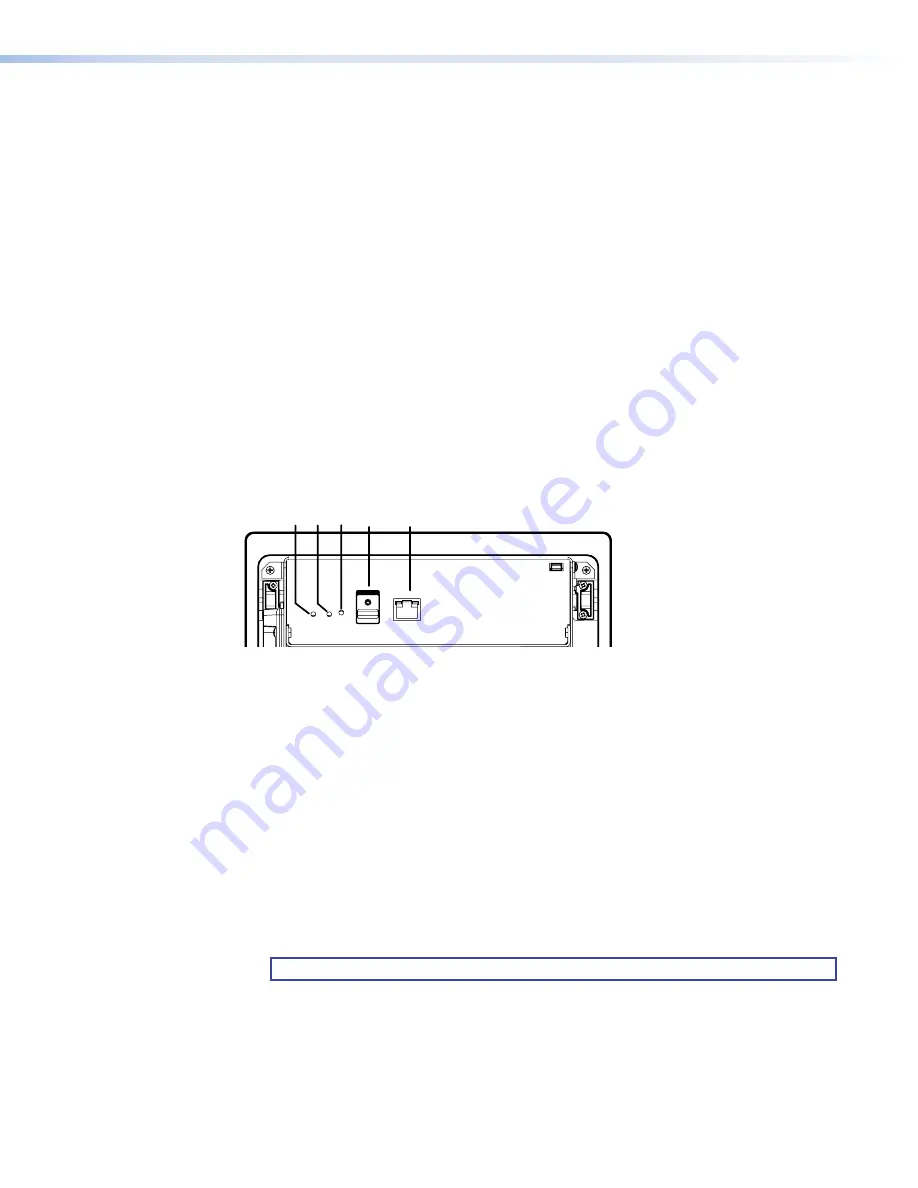
Figure 3 shows the TLP Pro 725C base panel. The TLP Pro 525C is very similar.
e
e
LAN / PoE
275 mA
USB
RESET
MENU
D
D
D E
E
E
A
A
AB
B
B C
C
C
Figure 3.
TLP Pro 725C Base Panel
A
Menu button
— Pressing the
Menu
button activates the setup menu (see
B
Reset button
— Pressing the
Reset
button allows the unit to be reset in any of three
different modes and can also be used to toggle between enabling and disabling the DHCP
client (see
C
Reset LED
— Provides feedback about the reset status when the user presses the
Reset
button (see
).
D
USB port
— Compatible with USB 2.0.
E
LAN/PoE port
— The TLP Pro 725C must be powered by a PoE power injector through
this port. Connect the touchpanel to a PoE power injector using a twisted pair cable,
terminated with an RJ-45 connector. Connect the power injector to the LAN through a
nework switch.
The network port has two LEDs. The green LED lights steadily to indicate that the
touchpanel is connected correctly to a network. The yellow LED blinks to indicate that data
is being passed to or from the touchpanel.
NOTE:
The power injector must be purchased separately.
Communication LED
Light sensor
Activation Switch
Speaker
figure 3
Menu button
Reset button
Reset LED
USB port
LAN/PoE port
TLP Pro 525C and 725C Series Touchpanels • Panel Features
6


