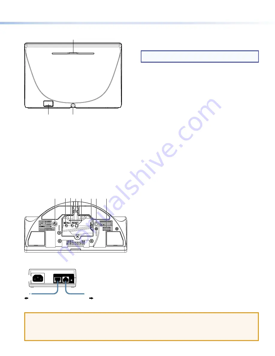
Rear Panel Features
A
A
B
B
C
C
Figure 2.
TLP Pro 725T Rear Panel
A
Status light
— Can be programmed to provide system feedback:
•
Light red or green
•
Blink or light continuously
For information about programming this light, see the
Global Configurator Help File
or the
Global Scripter Help File
.
B
USB-A port
— Compatible with USB 2.0. The port is concealed behind a plastic cover, which can be removed with a small,
flat-bladed screw driver.
C
Cable guide
— The LAN/PoE cable is inserted through this hole at the back of the base (see
LAN/PoE connector
below).
Base
Figure 3 shows the base of the TLP Pro 725T series models. The base of the TLP Pro 1025T series models are very similar.
F
F
A
A
B
B D
D E
E
G
G
C
C
A
A
Figure 3.
TLP Pro 725T Base
A
Mounting hole
(2) — See
Mounting
on the previous page.
B
Menu button
— Activates the setup menu (see
Setup Menu
on
the following page).
C
Reset button
— Initiates one of three reset modes for the unit
(see
Reset Modes: a Brief Summary
on the following page).
D
Cable guide
— The LAN/PoE cable is inserted through this hole
at the back of the base.
E
Reset LED
— Indicates power status and reset status of the
device (see
Reset Modes: a Brief Summary
on the following
page).
F
LAN/PoE Connector
— Attach the LAN/PoE cable to this RJ-45
port. The power injector must be purchased separately. Figure 4
shows the Extron XTP PI 100. Your power injector may look
different.
Connect a straight-through Ethernet cable from the power
injector to a switch or router (see figure 4,
1
). This cable
carries network information from the switch or router to the
power supply input. A second straight-through cable carries the
network information and 48 VDC from the power injector to the
touchpanel (
2
). Connect the IEC power cord to a convenient
100 VAC to 240 VAC, 50-60 Hz power source (
3
).
G
Speaker
— A single speaker provides audible feedback for the
user.
ATTENTION:
•
Do not power on the touchpanels or control processors until you have read the
ATTENTION
in the “Base” section of
the
TLP Pro 725 and TLP Pro 1025 Series User Guide
.
•
Ne branchez pas les écrans tactiles ou les contrôleurs avant d’avoir lu la mise en garde dans la section « Base » du
TLP Pro 725 and TLP Pro 1025 Series User Guide
.
100-240V
~
50-60Hz
0.4A MAX
XTP
PWR
XTP PWR
To network switch
To touchpanel
1
1
2
2
3
3
Figure 4.
Connecting to a Power Injector
NOTE:
Figure 2 shows the TLP Pro 725T series rear panel.
The TLP Pro 1025T series rear panels are very similar.
3
Product Category


