


Extron • System 8/10 P
LUS
• User’s Manual
Multiple Switcher Operation
DIP Switch Types
Before going into the switch setups, let us first explain that there are different
types of DIP switches, some "slide" and some "rock". Your System 8/10 P
LUS
could have either type DIP switch. Although they operate differently and are
labeled differently, they are simply on/off (open/closed) switches. Regardless of
the type of switch, we will show the positions as "up" or "down" and will use
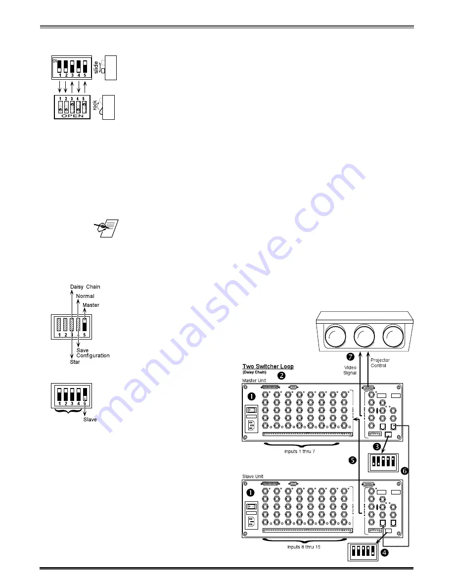
arrows to show the switch position. The illustration to the left shows two types of
switches having the same configuration. Throughout this manual you may see
either type of switch, however, the switch positions will be the same.
Looping Two Switchers
A simple example of using multiple switchers is to use two System 8/10 P
LUS
switchers. As explained on the previous page, the switcher feeding the projector
is the Master and the output of the Slave is one of the inputs to the Master.
1. See the figure below. Remove the power connections from both switchers and
decide which unit will be the Master Unit and which the Slave.
2. Disconnect all communications devices from the Master Unit.
_____ The only communications device that a Slave switcher can have connected is a
contact closure Manual Remote control (if required).
3. On the Master Unit, locate the DIP switches labeled "Address" in the lower right
corner of the rear panel. Set switches #3 and #5 up, and #1, #2 and #4 down.
(Switch #4 must be set to the "down" position until Step 9.)
4. On the Slave Unit, locate the Address DIP switches and set switches #1, 2, 3
and 4 up, and set switch #5 down for Slave Mode.
5. Connect the video output of the Slave Unit to
the last input of the Master Unit.
6. Connect an RJ11-to-RJ11 cable from the
"System Intercom Out" connector of the Master
to the "System Intercom In" connector of the
Slave.
7. Connect the video outputs
from the Master Unit to the
video inputs of the
projector. (Go to Chapter 3
for the detailed projector
connections.)
8. To save the configuration
first turn the Slave On, and
then turn the Master On.
Wait at least 10 seconds
for the Master Unit to save
the configuration to
memory.
9. On the Master Unit, set
Address switch #4 to
Normal, or "Up" position.
10. Make any necessary
connections and put both
switchers to normal
operation.
5-2
Looping
Address
(#0)
1 2 3 4 5
1 2 3 4 5
im Vertrieb von
CAMBOARD Electronics
www.camboard.de
Tel. 07131 911201
Fax 07131 911203


