Extron electronics PoleVault PVS 204SA Скачать руководство пользователя страница 3

Quick Start — PVS 204SA

Installation

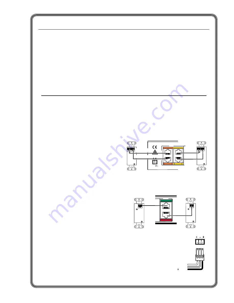
This Quick Start section deals specifically with 

quick connectivity and installation of the 

PVS 204SA PoleVault

 switcher.  At this stage, 

it is assumed that all of the necessary cable 

routing has been completed, and that projector 

ceiling hardware (e.g. ceiling mounts, projector 

poles, projector mounting kits) and output 

devices have been installed.  Also, any PVT 

transmitters should already be installed (but not 

yet connected) following the relevant supplied 

instruction manuals.

Step 1

Remove power from the switcher and any input, 

output, and control devices that are to be used in 

this installation.

Step 2

Using the supplied colored labels, label both ends 

of all audio/video input cables.  Ensure that the 

labels used match the input signal type that the 

cable will carry.  See chapter 2, “Installation”, 

“Labeling and connecting the A/V input cables” 

section, for wiring diagrams and input color 

coding table.

N


In some installations it may be prudent to 
label the cables before routing them.

Step 3

Connect input devices via PVT transmitters to 

the RJ-45 inputs on the rear of the PVS switcher.  

See chapter 2, “Installation”, “A/V input 

connections” section, for details and wiring 

diagrams. 

N


Labeling the cables correctly using the 
color code will make this step easier.

Inputs 1 and 2:


RGB video and audio

.

N


Two cables (A and B) are needed for each 
RGB input.  Do not cross connect them.

PVT RGB D

Input #2

PVT RGB D

Input #1

POWER

12V         
3A  MAX

I

N
P
U
T
S

RGB

RGB Input Connectors on

Rear Panel of PVS 204SA

Cable from 

PVT Output A

Cable from 

PVT Output B

B

A

A

B

Rear Panel

Rear Panel

1A

2A

1B

2B

Cable from 

PVT Output A

Cable from 

PVT Output B

Inputs 3 and 4:

  Composite video and audio.

VIDEO

PVT CV D

Input #3

Cable from 
PVT Output

PVT CV D

Input #4

Rear Panel

Rear Panel

Composite Video Input

Connectors on

Rear Panel of PVS 204SA

Cable from 
PVT Output

3

4

Step 4 (optional)

Connect a mono audio source 

to the Aux/Mix audio input on 

the rear panel to mix a line-

level audio signal with 

the selected input’s audio. 

N


This channel is always active.

AUX/MIX IN

+ Positive

– Negative

Ground

FCC Class A Notice

Note:  This equipment has been tested and found to comply with the limits for a Class A digital 

device, pursuant to part 15 of the FCC Rules.  These limits are designed to provide reasonable 

protection against harmful interference when the equipment is operated in a commercial  

environment.  This equipment generates, uses and can radiate radio frequency energy and, if not 

installed and used in accordance with the instruction manual, may cause harmful interference 

to radio communications.  Operation of this equipment in a residential area is likely to cause 

harmful interference, in which case the user will be required to correct the interference at his own 

expense.

N


This unit was tested with shielded cables on the peripheral devices.  Shielded cables must be used 
with the unit to ensure compliance.

Содержание PoleVault PVS 204SA

Страница 1: ...PVS 204SA PoleVault Switcher 68 1217 01 Rev D 09 08...

Страница 2: ...m machen da im Inneren des Geh uses dieses Produktes gef hrliche Spannungen die nicht isoliert sind und die einen elektrischen Schock verursachen k nnen herrschen Achtung Lesen der Anleitungen Bevor S...

Страница 3: ...for each RGB input Do not cross connect them PVT RGB D Input 2 PVT RGB D Input 1 POWER 12V 3A MAX I N P U T S RGB RGB Input Connectors on Rear Panel of PVS 204SA Cable from PVT Output A Cable from PV...

Страница 4: ...llation Mounting the Switcher section for details Step 10 Restore power to all devices FRONT REAR Input Cables from Transmitters AV control 1B 1A I N P U T S 2B 3B PO WE R 12V 3A MAX VID EO 3B VID EO...

Страница 5: ...necting speakers to the PVS 204SA 2 12 Labeling the A V Inputs 2 13 Labeling and connecting the A V input cables 2 13 Labeling the PVT Decora face plates 2 14 Final Setup 2 14 Chapter 3 Operation and...

Страница 6: ...Communication 4 1 RS 232 Programmer s Guide 4 2 Host to PVS communications 4 2 PVS initiated messages 4 2 Error responses 4 3 Using the command response tables 4 3 Symbol definitions 4 3 Factory defau...

Страница 7: ...PVS 240SA 1 Chapter One Introduction About this Manual About the PVS 240SA Application Diagrams...

Страница 8: ...ch can be located up to 100 30 m away The signals can be sent over Extron Enhanced Skew Free A V UTP cable or any CAT 5 5e or 6 shielded twisted pair STP unsheilded twisted pair UTP or foil shielded t...

Страница 9: ...8 ohm audio outputs through the integrated audio amplifier Executive Mode To prevent unauthorized access the switcher panel can be locked executive mode via the front panel or RS 232 An LED on the fro...

Страница 10: ...iver Ceiling Speakers AU DIO IN L R VID EO IN CO MP UT ER IN AU DIO IN CO MP UT ER IN AU DIO IN 4 4 7 1 1 1 3 2 8 9 CO NF IG DI SP LA Y VO LU ME 1 2 3 4 ON OF F TCP IP Network PVS 204SA PoleVault Swit...

Страница 11: ...MPU TE R IN AU DI O IN TP S T RGB CO NF IG DI SP LA Y VO LU ME 1 2 3 4 ON OF F TCP IP Network MIC IN MLP 10 1 AAP MUTE ACTIV E PVS 204SA PoleVault Switcher Extron PoleVault System MLP 101 AAP Mic to...

Страница 12: ...PVS 204SA Switcher Introduction 1 6 Introduction cont d...

Страница 13: ...PVS 240SA 2 Chapter Two Installation UL Safety Guidelines Mounting the Switcher Rear Panel Features and Cabling Speaker Configuration Labeling the A V Inputs Final Setup...

Страница 14: ...ng The wide blade or the third prong are provided for your safety If the provided plug does not fit into your outlet consult an electrician for replacement of the obsolete outlet 10 Protect the power...

Страница 15: ...E Tx A B C Rx IR 12V 10V POW ER 12V 3A MAX US LISTE D 17TT AUDIO VIDE O APPA RATU S RGB VIDE O RGB VIDE O Bottom Plate Filler Plate Front Plate Top Plate Front towards screen Figure 2 1 Installing th...

Страница 16: ...When all other cables have been connected plug the captive screw connector into the 2 pole female connector a to connect the switcher to the 12 VDC power source The front panel power LED lights while...

Страница 17: ...type To ensure correct cable identification and connection during installation a sheet of color coded cable labels is supplied See Labeling the A V Inputs later in this chapter for details on how to...

Страница 18: ...VIDEO PVT CV D Input 3 Cable from PVT Output PVT CV D Input 4 Rear Panel Rear Panel Composite Video Input Connectors on Rear Panel of PVS 204SA Cable from PVT Output 3 4 Figure 2 7 Connect the correc...

Страница 19: ...connector as shown at right N This audio input signal is present regardless of the selected input on the switcher The audio level is not affected by the program volume For wired microphones connect an...

Страница 20: ...ends PVS 204SA Switcher Rear Panel L R AUX MIX IN DO NOT GROUND OR SHORT SPEAKER OUTPUTS 1B 1A I N P U T S O U T P U T S 2B 2A 4 3 RS 232 MLC IR DC VOL 4 8 Ohms AMPLIFIED OUTPUTS VOL MUTE Tx A B C Rx...

Страница 21: ...ill control the projector via RS 232 and the PVS 204SA by hardwired IR An IR driver for the PVS 204SA is available on the Extron website Figure 2 10 Connecting an MLC 52 RS series controller N Connect...

Страница 22: ...PVS 204SA The range is 0 to 10 V where 0 V is mute and 10 V is maximum volume When connected the external volume control module is the sole volume controller N Do not control the PVS volume via RS 232...

Страница 23: ...mum output load of 4 ohms Speaker Configuration Speaker arrangement examples Ceiling and program speakers can be arranged several different ways The following factors affect the choice of speaker plac...

Страница 24: ...8 Ohm Load 4 Ohm Total Load 4 Ohm Total Load 8 Ohm Total Load 8 Ohm Total Load Two 8 ohm speakers wired in parallel equal a 4 ohm load Two 4 ohm speakers wired in series equal an 8 ohm load L R 4 8 O...

Страница 25: ...n around the cable allowing the signal type name to be easily read Figure 2 17 Wrap the label around the cable colored part first 2 Repeat step 1 for the other end of the cable using the same label ty...

Страница 26: ...tup should look similar to the figure below Ensure all connections are correctly made and secure N Refer to the MLC device user s manual for full MLC installation configuration and operating details P...

Страница 27: ...Chapter Three Operation and Setup Front Panel Features and Operation Setting Switcher Modes Auto Switching Setting Up and Optimizing the Audio Resetting the Switcher Front Panel Security Lockout Exec...

Страница 28: ...ed audio and video input The corresponding green LED lights and remains lit while the input is selected These buttons are also used to configure the switcher See Setting Switcher Modes later in this c...

Страница 29: ...tcher and separate switcher The default setting is single switcher mode Single switcher mode This mode makes the PVS function as a 4x1 switcher In single switcher mode the RGB video output is inactive...

Страница 30: ...highest numbered active input regardless of the signal format RGB or composite video For example if input 2 RGB is currently active and then 4 composite video becomes active the input automatically s...

Страница 31: ...by having the MLC increase the volume or by a potentiometer connected to the DC Volume port on the rear panel If an MLC 104 IP Plus is connected to the PVS simply rotate the volume knob clockwise unt...

Страница 32: ...clip LED flashes results in a distorted output signal clipping 3 When the minimum 18 dB or the maximum 24 dB is reached the Min Max LED see figure 3 6 lights red and flashes for approximately 0 3 seco...

Страница 33: ...only with a range from 10 dB to 10 dB By default the bass and treble have been set at 0 dB See chapter 4 Serial Communication for details on RS 232 control The loudness on off default off switch and...

Страница 34: ...dicate lockout To turn executive mode on or off via the front panel 1 Press and hold input selection buttons 1 and 4 simultaneously for 4 seconds see figure 3 8 2 Release the buttons when the input se...

Страница 35: ...PVS 204SA 4 Chapter Four Serial Communication RS 232 Programmer s Guide Updating Firmware...

Страница 36: ...line Ring Pin 5 Computer s signal ground Sleeve Figure 4 1 Pin out diagram for 2 5 mm mini cable TRS plug when connecting to the front panel Config port N Firmware updates can be made only via the fro...

Страница 37: ...SCII codes the PVS s responses to the host and a description of the command s function or the results of executing the command Upper and lower case characters may be used interchangeably in the comman...

Страница 38: ...dB X 18 to 24 input gain and attenuation readout in dB X1 10 through 10 power amp gain readout in dB X1 Status 1 single mode 2 separate switcher mode X1 0 thru 20 power amp attenuation adjustment rang...

Страница 39: ...gain X G In X Aud X Show an input s audio level Set the current input s gain X G In X Aud X Set the current input s gain in dB Set the current input s attenuation X g In X Aud X Set the current atten...

Страница 40: ...or IR remote control only Only volume adjustment is available via the front panel This command is equivalent to pressing and holding front panel buttons 1 and 4 View the executive mode status X Exe X...

Страница 41: ...output mode status 18 PreAmpMod X View the audio outputs 1 dual mono 2 stereo N This command indicates whether the Audio Output Mode DIP switch on the rear panel of the PVS 204SA is set to Stereo mode...

Страница 42: ...ame and location for later use 2 Locate on the Web site the appropriate firmware file PVS 204SA you want to update It has a filename ending in s19 PVS204_Vxxx s19 where Vxxx indicates the version numb...

Страница 43: ...nication PRELIMINARY 6 When the browser window opens click Browse to locate and select the firmware file 7 Select the firmware file and click Open to open the file 8 Click Upload to upload the firmwar...

Страница 44: ...n cont d PVS 204SA Serial Communication 4 10 PRELIMINARY 9 Wait until the status bar indicates completion The note Transfer Complete is shown and the unit resets itself 10 Click Exit to exit the progr...

Страница 45: ...A Appendix A Reference Material Specifications Part Numbers and Accessories Audio Block Diagram Audio Reference Levels...

Страница 46: ...ncy 30 Hz to 170 Hz DC offset max allowable 1 0 V Video output RGB Number signal type 1 VGA UXGA RGBHV RGBS follows input type Connectors 1 15 pin HD female Nominal level 0 7 Vp p for RGB Minimum maxi...

Страница 47: ...transmitters Connectors 4 female RJ 45 2 shared with RGB inputs 2 shared with composite video inputs N 0 dBu 0 775 Vrms 0 dBV 1 Vrms 0 dBV 2 dBu Audio preamplifier Input gain adjustment 18 dB to 24 d...

Страница 48: ...ools 3 deep rack shelf part 60 190 20 RSF 123 or 60 604 20 RSB 123 Also furniture mountable with an optional MBU 123 mini under desk mounting kit part 70 212 01 or above projector mountable with optio...

Страница 49: ...GB video transmitter 70 579 0x 70 580 0x Decora Wall Plate Models PVT CV D composite video transmitter PVT RGB D RGB video transmitter 70 579 0x 70 580 0x Rack Mounted Transmitters PVT CV composite vi...

Страница 50: ...Woofer 42 073 0x SI 28W Two Way In Wall Speakers 8 Woofer 42 069 03 Cable accessories Accessory Part number CFG cable 9 pin D female to 2 5 mm TRS configuration cable 70 335 01 MLC IR RS 232 cable pro...

Страница 51: ...ne Level Input Tone Controls Volume Treble Bass Loudness High Pass Filter ON OFF ON OFF Input Channel Gain High Pass Filter On Off DIP Switch Stereo Dual Mono DIP Switch Software Controlled Software S...

Страница 52: ...8 dBu 2 dBV 0 794 V 0 2 dBu 1 dBV 0 891 V 1 2 dBu 0 dBV 1 000 V 2 2 dBu 1 dBV 1 122 V 3 2 dBu 2 dBV 1 259 V 4 2 dBu 3 dBV 1 413 V 5 2 dBu 4 dBV 1 585 V 6 2 dBu 5 dBV 1 778 V 7 2 dBu 6 dBV 1 995 V 8 2...

Страница 53: ...isuse improper handling care electrical or mechanical abuse abnormal operating conditions or non Extron authorized modification to the product If it has been determined that the product is defective p...

Страница 54: ...7 FAX Extron EMEA 800 3987 6673 Inside Europe Only 31 33 453 4040 31 33 453 4050 FAX Extron Asia 800 7339 8766 Inside Asia Only 65 6383 4400 65 6383 4664 FAX Extron Japan 81 3 3511 7655 81 3 3511 7656...

Отзывы: