


5
Optimizing Video
Setting the Peaking and Level on the MTP/HDMI U R
Image sharpness is adjusted with the front panel Peaking adjustment knob.
This applies only to the analog side of the device. Increased peaking compensates for mid- and high-frequency detail loss.
Minimum setting (full counterclockwise) is zero peaking. Image brightness is adjusted using the Level adjustment knob.
NOTE:
To avoid possible video loss due to errors in the video format detection, the user should always start with minimal level
and peaking, then increase values as required.
Setting the Skew on the MLS 608 D
Adjusting output skew between the
MLS 608 D and the receiver:
1.
Connect an oscilloscope (preferred) or a monitor
(acceptable) to the RGB output on the MTP/HDMI U R.
2.
Apply a crosshatch test pattern to input 1, 2, or 3
on the MLS 608 D.
3.
Use the test equipment or examine the video image
with a critical eye to determine which video signal
(red, green, or blue) is most shifted to the left.
4.
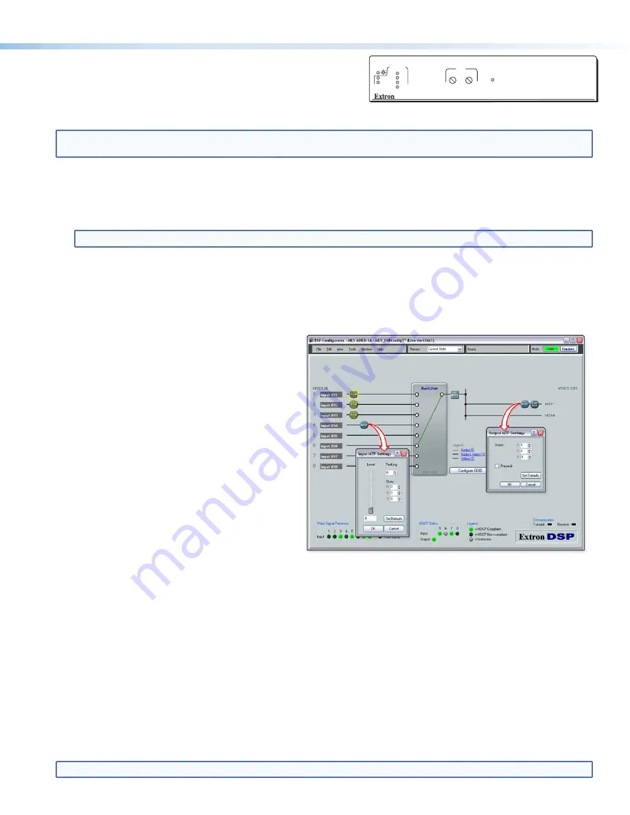
Within the DSP Configurator program, click
View > Video I/O
(or press <F4>) to access the MLS workspace view. Double-click
MTP on the output (right) side of the workspace view. The Output MTP Settings dialog box appears (see image above).
5.
Adjust the furthest left video signal by using the up and down arrows for the relevant signal color, and repeat as needed until
all three colors are aligned correctly.
Adjusting input skew if using Input 4
Follow the steps 1 to 3 as given in “Output skew”, above. Then:
1.
Within the DSP Configurator program, click
View > Video I/O
(or press <F4>) to access the MLS workspace view.
Double-click MTP on the output (right) side of the workspace view. The Output MTP Settings dialog box appears.
2.
Adjust the furthest left video signal by using the up and down arrows for the relevant signal color, and repeat as needed until
all three colors are aligned correctly.
Selecting the MLS 608 D Output Prepeaking
1.
Click
View > Video I/O
(or press <F4>); this changes the window to the MLS workspace view. Double-click on the MTP on
the output (right) side of the workspace view. The Output MTP Settings dialog box appears.
2.
Toggle the Pre-peak box on or off as desired
.
NOTE:
For other video configurations, such as RGB delay or input video format swapping, see the DSP Configurator Help file
.
Adjusting level and peaking between the MLS 608 D and the receiver
1.
Connect an oscilloscope (preferred) or a monitor (acceptable) to the RGB output of the MTP/HDMI U R receiver.
2.
If using an oscilloscope, apply a white field test pattern to inputs 1, 2, or 3 on the MLS 608 D. The Extron VTG 300 or VTG 400 is
recommended to provide the test pattern.
3.
If using a monitor, apply a grayscale or color bars test pattern to the input.
NOTE:
The signal applied should be an RGB signal.
4.
Observe the oscilloscope (or monitor) while you adjust the front panel input level and peaking controls to compensate for
signal loss between the MLS 608 D and the MTP/HDMI U R.
Setting level and peaking via software if using Input 4 on the MLS 608
Follow the steps 1 to 3 as given in “Adjusting level and peaking...” above. Then:
1.
Start the DSP Configurator software program and connect to your device.
See page 7
for software installation details.
2.
Click
View > Video I/O
(or press <F4>); this changes
the window to the MLS workspace view. Double click
on the MTP on the input 4 (left) side of the workspace
view. The Input MTP Settings dialog box appears (see
image at right).
3.
Observe the oscilloscope (or monitor) and adjust the
level using the slider. Adjust the peaking by using the
up and down arrows. Disconnect test equipment when
finished.
MTP/HDMI U R
RGB
PEAKING
LEVEL
DIGITAL SIGNAL
ANALOG
SIGNAL
AUDIO
RS-232
VID
Y/C
YUV
RGB


