IRL 20 • Installation and Operation
IRL 20 • Installation and Operation
Installation and Operation
2-3
2-2
UL Requirements
1.
This unit is not to be connected to a centralized DC power
source or used beyond its rated voltage range.
2.
The IRL 20 must be installed with accordance with the
National Electrical Code and with local electrical codes.
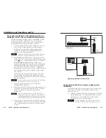
See the illustration at right for
pin assignments:
Other accessories such as an
Extron control module (IRCMs,
ACMs, RCMs) or an SCP
control pad can be connected to
the other 5 poles of
this captive screw
connector.
Front and Rear Panel Features
Front
Rear
+12V
G
N
D
C
M
Mod
IR
SCP
+12V
G
N
D
C
M
Mod
IR
SCP
IR SNSR
IRL 20
GND
SIG
+5V
2
3
1b
1a
1
IR signal receivers
1b
and indicator LED
1a
(behind the panel) — The sensors that
receive incoming IR signals are behind the
red, plastic, front panel lens near the middle;
toward the left is a green LED that blinks
when an IR signal is received by the IRL 20.
The angles (+/- 40°) and maximum distance
(up to 30') recommended for best reception
of incoming signals are shown in the
illustration at right.
2
Communications connector
— Use this
10-pole connector to connect the IRL 20 to
other Extron devices. Both halves of the
connector function the same way (either can
be used as an input or an output), so they
are interchangeable.
Connectors are included with the IRL 20, but the cable
must be purchased separately. See the illustration on the
next page for reference, and see appendix A for cable part
numbers and conductor gauges.
Install a 3.5 mm, 5-pole captive screw connector on one end of
an Extron Comm-Link cable, and plug it into the left or the right
half of this connector. Wire both ends of the cable identically
(ground pin to ground pin, modulated IR to modulated IR, etc.).
Plug the other end of the cable into the appropriate connector
on an Extron MediaLink Controller (MLC), MediaLink Switcher,
System 5 IP Switcher, or AVT 100.
IRL 20 Front
40
40
30 feet
max.
Extron
IR Remote
IR SNSR
GND
SIG
+5V
+5 VDC
Demodulated IR
Ground ( )
+12V
GND
C
M
M
od
IR
SCP
+12V
GND
C
M
M
o
dIR
SCP
+12 VDC power
Modulated IR output
Control module signal
SCP control pad signal
Ground ( )
The Extron switchers and the AVT 100 devices provide 12 VDC
on pin B and a ground on pin A, so there is no need for an
additional power supply.
If the IRL 20 is used with an MLC 104 Series or
MLC 226 Series controller, do not power the IRL 20 from
the MLC: connect an external 12 VDC power supply
(such as Extron part #70-055-01) to those pins.
Connect a maximum of one (1) IRL 20 to a device. Do
not connect more than one IRL 20 or IR Link (either in
parallel or in series) to a switcher, MediaLink Controller,
or AVT.
3
IR Sensor port
— If the installation requires an IR pickup
device that is even less visible than the IRL 20, you can cable an
Extron IR Sensor (part #70-223-01) to this port, hide the IRL 20
within furniture, and place the IR Sensor’s receiver head in the
line of sight of the Extron remote control.
The IR Sensor has a 6' (1.8 m) cord to allow it to
be placed a short distance away from the IRL 20.
The adhesive backing on the back of the receiver
head makes it easy to install without tools (aside
from the small screwdriver needed to fasten the
connector to the end of the wire. See the
diagram at left for pin configurations.
The IR sensor has a 6' (1.8 m) cord, but the maximum
cable length for the IR Sensor is 21' (6.4 m). Do not cut
the IR sensor’s cable or extend it beyond 21 feet.


