IR Link • Installation and Operation
IR Link • Installation and Operation
Installation and Operation
Preparing the Site and Installing the Wall Box
The IR Link can be installed in a one-gang electrical wall box or
a mud ring-type mounting bracket. Choose a location that will
allow cable runs without interference. Allow enough depth for
both the wall box and the cables. The box should be at least 1.5”
(3.8 cm) deep to accommodate the circuit board, connectors, and
cables. Install the cables into the wall, furniture, or conduits
before installing the IR Link.
The installation must conform to national and local electrical
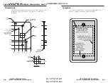
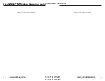
codes and to the IR Link’s size requirements. A dimensional
drawing and an actual-size cut-out template are provided in
appendix A of this manual.
1.
Cut out the center portion of the cut-out template that
corresponds to the type of installation being used (wall box
or no wall box). If installing a mud ring-type mounting
bracket, use the template that came with the mud ring.
2.
Place the template (or the wall box) against the installation
surface, and mark the guidelines for the opening on the
wall or furniture.
3.
Cut out the material from the marked area.
4.
Check the opening size by inserting the wall box into the
opening. The box and the IR Link’s circuit board should
fit easily into the opening. Enlarge or smooth the edges of
the opening if needed.
5.
Feed cables through the wall box punch-out holes, and
secure them with cable clamps to provide strain relief.
6.
Exposed cable shields (braids or foil) are potential sources
of short circuits. Trim back and/or insulate shields with
heat shrink.
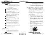
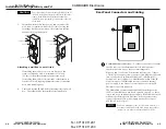
Metal Wall Box
Screw
Braided Shield
Install Cable
Foil Shield
Cable Clamp
Grounding outer braided and foil shields
2-3
Installation Overview
CAUTION
Installation and service must be performed by
authorized personnel only. These units must be
installed in accordance with the National Electrical
Code and with local electrical codes and used with
UL approved electrical boxes. See “UL Require-
ments” on this page.
To install and set up an IR Link, follow these steps:
1
Turn the equipment off. Make sure that the IR Link is
disconnected from the power source.
2
Select the site and run cables through the wall or furniture
to where the IR Link will be installed.
3
Prepare the site (cut a hole, install an electrical box or mud
ring/mounting bracket). See the instructions in this
chapter for site preparation details. Cable clamps should
be used to hold the cables in place for strain relief. Trim
back and/or insulate exposed cable shields with heat
shrink to reduce the chance of short circuits.
4
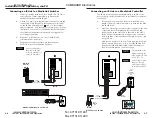
Attach connectors to the cables. See “Rear Panel
Connectors and Cabling” in this chapter.
5
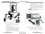
Attach the terminated cables to the IR Link’s rear panel
connectors and, if applicable, to the remotely controlled
Extron device.
6
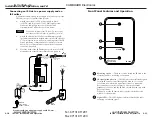
Verify correct wiring and cabling, and test the system: con-
nect the devices to a power source, turn them on, aim an IR
remote control at the IR Link, and check for the appropri-
ate response at the remotely controlled Extron device.
7
Disconnect all the devices from the power source(s), and
correct any cabling errors.
8
Being careful not to damage the cables, place the IR Link
onto/against the wall or furniture and secure it to the wall
or furniture with the provided screws.
9
Restore power to the system.
2-2
included with the IR Link; the installer is responsible for
obtaining and installing the box.
3.
These units must be installed in accordance with the
National Electrical Code and with local electrical codes.
UL Requirements
1.
This device is not to be connected to a centralized DC
power source or used beyond its rated voltage range.
2.
This unit must be installed in a UL listed junction box.
The UL approved electrical wall box (junction box) is not
im Vertrieb von
CAMBOARD Electronics
www.camboard.de
Tel. 07131 911201
Fax 07131 911203


