User Guide
IPL T PC1IPL T PC1i
IP Link
®
IP Link Power Control Interfaces
68-738-10 Rev.
B
09 11
Страница 1: ...User Guide IPL T PC1 IPL T PC1i IP Link IP Link Power Control Interfaces 68 738 10 Rev B 09 11 ...
Страница 2: ...verwenden sollten Sie alle Sicherheits und Bedienungsanleitungen genau durchlesen und verstehen Aufbewahren der Anleitungen Die Hinweise zur elektrischen Sicherheit des Produktes sollten Sie aufbewahren damit Sie im Bedarfsfall darauf zurückgreifen können Befolgen der Warnhinweise Befolgen Sie alle Warnhinweise und Anleitungen auf dem Gerät oder in der Benutzerdokumentation Keine Zusatzgeräte Verw...
Страница 3: ... a commercial environment This equipment generates uses and can radiate radio frequency energy and if not installed and used in accordance with the instruction manual may cause harmful interference to radio communications Operation of this equipment in a residential area is likely to cause harmful interference in which case the user will be required to correct the interference at his own expense N...
Страница 4: ... commands and examples of computer or device responses mentioned in this guide the character 0 is used for the number zero and O represents the capital letter o Computer responses and directory paths that do not have variables are written in the font shown here Reply from 208 132 180 48 bytes 32 times 2ms TTL 32 C Program Files Extron Variables are written in slanted form as shown here ping xxx xx...
Страница 5: ...essories 64 Mounting the IPL T PC1 Interface 64 Tabletop Use 64 Rack Mounting 64 Under desk Mounting 65 Glossary 67 Introduction 1 About this Guide 1 About the IPL T PC1 1 Features 1 Application Diagram 3 Installation and Rear Panel 4 Installation Overview 4 Rear Panels 5 Connecting Cables 6 RS 232 Port Cabling 6 Wiring the Local Area Network LAN Port 8 Wiring for IR Control 8 Wiring the Contact I...
Страница 6: ...IPL T PC1 Contents vi ...
Страница 7: ...rol serial device control IR device control and input sensing in a single device that can be mounted on a rack or behind a display device or kiosk The PC1 can be a stand alone control device or as one of many nodes in a distributed control system environment Features Remote powering a device on and off Centralized management features such as Telnet allow remote powering on and off of a plasma disp...
Страница 8: ...led using the web pages Simple Instruction Set SIS commands or Global Configurator Front panel lockout executive mode can also be scheduled by these methods Easy configuration and control You can easily control the PC1 using The Internet Explorer browser V5 5 or later A web based interface DataViewer or a standard Telnet client application Extensive library of device drivers Device drivers allow E...
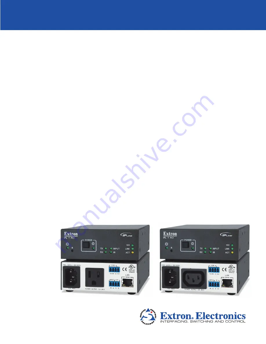
Страница 9: ...0 24 0V 50 60H z 10 A MAX PO WER OUTP UT 10 A MAX LA N CO M TX IN S G 5 V RX INPU T IR TCP IP Network ON Ethernet DVD AC Power RS 232 Plasma Display Remote User Control and Administrator Monitoring Extron IR Emitter Kiosk Button Extron IPL T PC1i Ethernet Control Interface Figure 1 Connection Diagram for an IPL T PC1 IPL T PC1 Introduction 3 ...
Страница 10: ...el to establish a link to the network see Wiring the Local Area Network LAN Port 5 Set up an IP address for the PC1 see HTML Configuration and Control or SIS Programming and Control 6 Plug an output device into the output power receptacle on the PC1 rear panel 7 If desired connect the output device to the serial COM port 8 If desired connect a contact closure device to the Input port 9 If desired ...
Страница 11: ...enable bidirectional RS 232 device control This serial port contains the following four pins in order from left to right on the rear panel transmission Tx receiving Rx ground _ and 5 V to tie hand shaking lines on the controlled device if needed d LAN connector and LEDs An Ethernet connection can be used on an ongoing basis to monitor and control the PC1 and the device connected to it see Wiring t...
Страница 12: ...nto a wall outlet and into the 3 prong male power connector on the PC1 rear panel The green Power LED lights and remain lit 2 Plug the Ethernet cable from the network into the LAN port on the rear panel The green Link LED on the connector lights 3 Plug the power cord of the output device to be controlled into the output receptacle on the PCI rear panel 4 If desired connect the output device to the...
Страница 13: ...rst three pins of the connector starting from the left a Connect the wire from the Receive port of the display to the first pin on the left of the connector which plugs into the PC1 Tx Transmit port b Connect the wire from the Transmit port of the display to the second pin of the connector which plugs into the PC1 Rx Receive port c Connect the ground wire from the display to the third pin of the c...
Страница 14: ...een White brown Brown Figure 6 RJ 45 Connector Wiring Wiring for IR Control If you intend to control the display device via infrared IR commands from the PC1 wire an Extron IR emitter to a 3 5 mm 2 pole captive screw connector provided and plug the 2 pole connector into the IR Signal and Ground pins pins 3 and 4 of the shared captive screw connector on the rear panel Alternatively you can wire the...
Страница 15: ...aptive screw connector provided and plug the connector into the two Input pins In and _ of the shared Input IR port connector on the rear panel Alternatively you can wire the contact closure device to pins 1 and 2 from the left of the provided 4 pole captive screw plug and if desired also wire an IR emitter to pins 3 and 4 of the same 4 pole connector see Wiring for IR Control on the previous page...
Страница 16: ...LED lights when RS 232 data is being transmitted The Rx LED lights when RS 232 data is being received c Input LED This green LED lights when the Input contact closure port is activated shorted d LAN status LEDs These three LEDs show the status of the Ethernet connection as follows 100 When lit indicates a 100 Mbs connection speed Otherwise the connection speed is 10 Mbs Link Lights steadily while ...
Страница 17: ...C1 takes approximately 2 minutes to store settings made via the front panel SIS commands or the web pages into its memory If you disconnect power from the PC1 less than 2 minutes after entering a setting your entry may be lost Setting Up Power Control of the Output Device To set up power control of the output device plugged into the PC1 output power receptacle 1 On the PC1 front panel press and re...
Страница 18: ...the unit by pressing the Reset button on the front panel This button is recessed and can be accessed with an Extron Tweeker or other small Phillips screwdriver CAUTIONS Review the reset modes carefully Use of the wrong reset mode may cause unintended loss of flash memory programming or a unit reboot The reset modes described on the following pages break all TCP IP connections by closing all socket...
Страница 19: ... Extron DataViewer or HyperTerminal 2 Immediately press the Reset button momentarily for less than 1 second NOTE Nothing happens if the momentary press does not occur within 1 second 3 Within 2 seconds of the momentary press press the key on the computer keyboard three times Result The RS 232 port is converted to a host port which allows the use of SIS commands and host responses No LEDs blink to ...
Страница 20: ...not occur within 1 second Result Reset mode 4 does the following Enables ARP program capability Sets the IP address back to factory IP settings Sets the subnet mask back to factory default Sets the gateway address back to factory default Sets port mapping back to factory default Turns DHCP off Turns events off Purpose and notes Mode 4 enables you to set IP address information using ARP and the MAC...
Страница 21: ...ruction Set SIS commands via Telnet SIS commands are discussed in detail in the SIS Programming and Control section Global Configurator GC 3 3 software enables you to configure and control the PC1 as well as set up output device monitoring and scheduling see the IPL T PC1 Setup Guide provided with your PC1 for information on setting up using GC 3 3 Configuring the Hardware for Ethernet Control To ...
Страница 22: ...dure CAUTION The PC1 must be configured with the factory default IP address 192 168 254 254 before you execute the ARP command as described below 4 On the computer access the command prompt as follows a From your Windows desktop Start menu select Run b On the Run window enter cmd The command window opens 5 At the command prompt enter arp s followed by the desired new IP address for the PC1 a space...
Страница 23: ...e the default settings of the PC1 IP address subnet mask and optionally administrator name and password in order to use the unit on an intranet LAN or on the Internet WAN After you have set up the PC1 for network communication you can reset the computer to its original network configuration IPL T PC1 LAN port defaults PC1 IP address 192 168 254 254 Gateway IP address 0 0 0 0 Subnet mask 255 255 0 ...
Страница 24: ... this section are for Windows XP For other Windows versions the screens may appear slightly different 1 Open the Network Connections page as follows a From the Start menu select My Network Places b From the Network Tasks side bar menu select View Network connections 2 Right click Local Area Connection then select Properties Figure 12 Network Connections Window IPL T PC1 HTML Configuration and Cont...
Страница 25: ...r computer below You will need to restore these settings to the computer later If the Obtain an IP address automatically radio button has been selected make a note of that 5 On the Internet Protocol TCP IP Properties window change your computer IP address temporarily so that it can communicate with the PC1 a Select the Use the following IP address radio button b Enter the following values as shown...
Страница 26: ...low for the procedure Once the PC1 has been reconfigured you can subsequently use an Ethernet intranet or Internet connection to configure or control it NOTE Both your computer and the PC1 must be connected to the same LAN Configuring the IPL T PC1 Using a Web Browser The default web pages that are preloaded on the PC1 are compatible with popular web browsers such as Internet Explorer version 5 5 ...
Страница 27: ...work administrator should provide the addresses to be used with this interface The PC1 can takes up to 2 minutes to store the new settings When the PC1 IP address is changed your computer loses communication with it and a screen appears indicating that the page cannot be displayed 5 Close the browser 6 After changing the IP settings of the PC1 restore the original TCP IP settings to your computer ...
Страница 28: ...mat enter the PC1 IP address followed by nortxe_index html Example 10 26 188 44 norte_index html See the IPL T PC1 Setup Guide delivered with your PC1 for information on using Global Configurator NOTE If a password has been set the Enter Network Password dialog box opens If no password has been set the PC1 web page opens displaying the System Status page Skip steps 3 and 4 3 Enter the administrato...
Страница 29: ...e current settings Changes must be made via the Configuration web pages or SIS programming commands see SIS Programming and Control Personnel who have user access can view this page but cannot access the Configuration or File Management pages Figure 17 System Status Screen IPL T PC1 HTML Configuration and Control 23 ...
Страница 30: ... pages select the Configuration tab There are seven web pages that can be accessed from the Configuration page They are listed in the sidebar menu at the left of the page These pages are described in the following sections Specifying system settings On the System Settings page you can set the date and time change the IP address information for the PC1 and enable or disable lock mode Figure 18 Syst...
Страница 31: ...tworks into a series of subgroups subnets The mask is a binary pattern that is matched up with the IP address to turn part of the host ID address field into a field for subnets You can enter a new subnet mask address using the same format that is used for the IP address To change the IP address settings 1 In the IP Settings section make entries or selections in the available fields as desired 2 Wh...
Страница 32: ... Sunday in February Daylight saving time should be turned off in equatorial Brazil 3 When you have made all the desired changes in the Date Time Settings section click the Submit button at the bottom of the section The new date and time settings are displayed in the fields in which you entered them If you want to discard your new entries without submitting them and restore the previous settings cl...
Страница 33: ...acle is named Receptacle 1 Select the On or Off radio button to power the connected device on or off Click Submit to implement your changes If you click Cancel before submitting your selections your entries are reset to the last saved parameters Using the IR Drivers page The IR Drivers page lets you view the IR drivers that have been uploaded to the PC1 via the File Management page see Managing Fi...
Страница 34: ...rator and user access levels The administrator password gives access to all IPL T PC1 web pages enabling the administrator to configure the PC1 The user password provides access only to the System Status web page If you are logged in as user you see only the Status tab with the System Status page You cannot make any configuration changes To assign passwords 1 On the Configuration page select Passw...
Страница 35: ... in the Re enter User Password field 6 Click Submit to set the passwords Removing passwords To remove a password 1 On the Configuration page select Passwords from the sidebar menu 2 In the Administrator Password or the User Password field delete the characters that are there and press the Spacebar to enter a space 3 In the Re enter Admin Password the Re enter User Password or both fields delete th...
Страница 36: ...ade in the Global Configurator software The e mail alert can notify up to 49 recipients at one time the Email Alerts page lets you enter up to 49 e mail addresses Figure 23 E mail Alerts Page Upper Portion 1 On the sidebar menu on the Configuration page click Email Alerts 2 On the Email Alerts page click the Edit button located to the right of the Mail IP Address field The page goes into Edit mode...
Страница 37: ...ecify that SMTP Simple Mail Transfer Protocol authentication is needed for the PC1 to send mail to the e mail server To set the PC1 to require SMTP authentication before the server accepts any e mail 1 To enable the SMTP authentication fields click the Edit button at the right of the Mail IP Address field The Edit button changes to Save 2 Select the SMTP Authentication Required check box located b...
Страница 38: ...wnload Center page click the Firmware link at the top of the left sidebar menu 4 On the Archives line at the top of the Firmware page click the letter I 5 On the next page that appears click the Download link at the right end of the IPL T PC1 or IPL T PC1i line 6 Fill in the required information on the next Download Center page and click the Download IPLTPC1 button 7 Click Run on the File Download...
Страница 39: ... Firmware Upgrade screen 4 Click Upload When the firmware upgrade is complete the Power LED on the unit blinks three times NOTES If you attempt to upload a file with an extension other than S19 the PC1 recognizes it as invalid and ignores it reverting to the last successfully uploaded firmware version The new firmware version number does not immediately appear on the Firmware Upgrade screen To ver...
Страница 40: ...dule on the sidebar menu on the Configuration page Figure 26 Schedule Page On the Schedule page When you click on a day On Off or the contents of any cell in the Current Schedule table a time or a dash a Set Schedule For section displays above the Scheduling section In this field you enter your settings for power or executive mode To close the Set Schedule For section without saving your entries i...
Страница 41: ...edule For section with Power On scheduled for 6 00 am Monday through Friday Figure 27 Set Schedule For Section Displayed for Receptacle 1 2 From the drop down menus select the time hour minutes and am or pm at which you want power turned on or off 3 Select the check boxes for the days of the week you want the receptacle to be turned on or off at the time you specified 4 When finished click Set to ...
Страница 42: ... example below front panel lockout has been scheduled to start at 7 30 pm Monday through Friday Figure 28 Set Schedule For Field for Executive Mode 2 From the drop down menus select the time hour minutes and am or pm at which you want executive mode enabled or disabled 3 Select the check boxes for the days of the week you want lock mode to be turned on or off at the time you specified 4 When finis...
Страница 43: ... the illustration below Sunday has been selected for scheduling Figure 29 Schedule Screen Showing Fields for Daily Receptacle Scheduling 2 In either the Power ON or Power OFF section select the hours minutes and am or pm from the menus and select the check boxes for the items you want to schedule 3 In the section in which you made your selections click Set to enter your choices The section closes ...
Страница 44: ... selected on the Scheduling table Managing Files The File Management screen allows you to upload and delete files including IR drivers from your computer or server File names must contain valid alphanumeric characters or underscores spaces and special characters symbols are not allowed Only personnel with administrator access can view the File Management page and make changes Uploading files to th...
Страница 45: ...ayed perform the Uploading files procedure described in the previous section to add a file to the directory The directory name appears at the top of the Files column preceded by a slash NOTE If no files are added to the new directory it is deleted when you open another directory To add more files to the directory click the directory name to open it then use the Uploading files procedure To exit th...
Страница 46: ...Include Using the Host SIS command type with no spaces SIS command to be processed by the IP Link N Figure 32 Example of the SSI Command In the figure above the N command is used to request the PC1 part number Query strings A query string is the portion of a URL that appears after the question mark The query string contains parameters or instructions for the web server to execute The basic format ...
Страница 47: ...part number of an IP Link device The figure below shows the HTML code that results from the SSIs shown in the above example html head title Example 1 title head h2 b HTML Example 1 h2 b body The following lines demonstrate how to read status from the IPLink Product IPLink Product Name b IPL T PC1 b br IPLink Product Description b One Switched 110v AC Receptacle with Serial and IR communication b b...
Страница 48: ... URL Alphanumeric characters 0 9 a z A Z Special characters _ Reserved characters NOTE When used for their reserved purposes these characters do not require encoding within a URL Figure 37 Characters that Do Not Require Encoding Reserved characters Reserved characters should not be encoded when they appear in their conventional meaning in a URL For example do not encode the slash when using it as ...
Страница 49: ...Tilde 7E 126 Left bracket 5B 91 Right bracket 5D 93 Grave accent 60 96 Accessing and Using Telnet Port 23 Telnet short for Telecommunications Network provides a way for you to connect to a computer or server in this case the PC1 interface on a network Once connected via Telnet you can send ASCII serial commands see the Command and Response Table for SIS Commands in the SIS Programming and Control ...
Страница 50: ...cted system you are prompted to log in as an administrator or a user Otherwise the system responds with a carriage return and line feed CR LF 5 Once you are connected you can enter SIS commands as desired for example 1 1PC power on or 1 0PC power off See the SIS Programming and Control section for more information on entering SIS commands 6 When you are finished entering commands to the interface ...
Страница 51: ...Connections 1 Check the network connections and make adjustments as needed The green Link LED lights steadily while a network connection is detected The yellow ACT LED blinks if there is activity on the network If these LEDs are not lit either the cable is faulty or not plugged in or the wrong type of cable is being used see Connecting the Hardware in the Installation and Rear Panel section 2 At t...
Страница 52: ...zed web based power management for A V systems Using Global Configurator software administrators can view the immediate status and power level of an output device schedule actions such as powering on and off monitor specified conditions and configure its ports To download the latest version of Global Configurator 3 from the Extron website 1 Select the Download tab on the Extron website home page 2...
Страница 53: ...r more characters per field No special characters are required to begin or end a command sequence When the PC1 determines that a command is valid it executes the command and sends a response to the host device All responses from the interface to the host end with a carriage return and a line feed CR LF which signals the end of the response character string A string is one or more characters Messag...
Страница 54: ...port number E13 Invalid value the number is out of range too large E14 Not valid for this configuration E17 System timed out E22 Busy E24 Privilege violation E25 Device is not present E26 Maximum number of connections has been exceeded E27 Invalid event number E28 Bad filename or file not found E30 Hardware failure followed by a colon and a descriptor number E31 Attempt to break port pass through ...
Страница 55: ...g on whether you are using Telnet or a web browser When using these commands through a web browser you can use the URL reference to shorten the examples URL refers to the full address of the control interface and web page reference including all path information that is http 192 168 100 10 myform htm To send any of the commands using a web browser you must prefix them with the full URL followed by...
Страница 56: ... must be set before standby X1 Group number 0 none 1 yellow 2 green 3 red The exponent designates the port number The color relates to setting groups via the front panel X1 Version typically listed to two decimal places that is n nn X1 Unit name The name of the PC1 is a text string of up to 24 characters drawn from the alphabet A Z digits 0 9 and minus sign or hyphen No blank or space characters a...
Страница 57: ...e setting the value does Example Command E CN Response Ipn X1 X2 Priority status for receive timeout 0 priority set to Send Data String command parameters 1 priority set to Configure Receive Timeout command parameters X2 Baud rate 300 600 1200 1800 2400 3600 4800 7200 9600 14400 19200 28800 38400 57600 or 115200 X2 Parity Only the first letter is needed O Odd E Even N None M Mark S Space X2 Data b...
Страница 58: ...amed n eml n can be 0 999 for example 1 eml 2 eml 999 eml This command overrides the file specified in the CR command If the value is 0 or a parameter is missing the file specified for the mailbox in the CR command is sent instead NOTE The SM command sends a default e mail message if the X4 file is not found X4 Default name a combination of the model name and the last three pairs of the interface ...
Страница 59: ...cimal number X7 Hardware MAC address the eight least significant hex nibbles converted into a single 32 bit decimal number NOTE This can be up to 10 digits X7 E mail account user name Maximum length is 31 characters This parameter is optional commas cannot be used as placeholders for it If it is omitted from an issued command any existing user account name is cleared X7 E mail account password Max...
Страница 60: ... Set2 X71 X X71 View scheduling E 2 X71 X SS W 2 2A X71 2A X SS X71 Ethernet Data Port Commands Set current connected port timeout E 0 X6 TC W 0 2A X6 TC Pti0 X6 View current connected port timeout E 0TC W 0TC X6 Set global IP port timeout E 1 X6 TC W 1 2A X6 TC Pti1 X6 View global IP port timeout E 1TC W 1TC X6 Information Requests NOTE An asterisk after a version number indicates the version tha...
Страница 61: ...odel UL date and time With tagged response verbose modes 2 and 3 Ver04 X1 plus web version model UL date and time Request interface part number N N 60 544 10 or 60 544 20 With tagged response verbose modes 2 and 3 Pno 60 544 10 or 60 544 20 Request model name 1I 1I IPL T PC1 or IPL T PC1i With tagged response verbose modes 2 and 3 inf01 IPL T PC1 Request model description 2I 2I Brief product descr...
Страница 62: ...X4 X4 Send e mail events file named in mailbox 24 E X4 SM W X4 SM Eml X4 Send e mail using a different file24 E X4 X7 X4 SM W X4 2C X7 2C X4 SM Eml X4 Web Browser specific Commands Read response from last URL cmd E UB W UB Response from command Mail Server Setup Commands Set mail server IP unit domain name and SMTP authentication24 E X1 X1 X7 X7 CM W X1 2C X1 2C X7 2C X7 CM Ipm X1 X1 X7 X7 View ma...
Страница 63: ...nge This is called a verbose wordy relationship between the interface and a connected device When the IPL T PC1 is connected to the computer via Ethernet verbose mode is disabled by default in order to reduce the amount of communication traffic on the network If you want to use the verbose mode with the PC1 connected via Ethernet you must set verbose mode to On each time you reconnect the computer...
Страница 64: ...sword is not entered If a correct administrator or user password is entered the unit responds with Login Administrator or Login User depending on the password that was entered If the administrator and user passwords are the same it defaults to administrator privileges Remapping Port Designations NOTE Duplicate port number assignments are not permitted that is Telnet and web cannot be the same Ente...
Страница 65: ... Commands Erase user supplied web page or file24 28 E filename EF W filename EF Del filename Erase current directory and its files24 28 E EF W 2F EF Ddl Erase current directory and its subdirectories24 28 E EF W 2F 2F EF Ddl List files from current directory E DF W DF See below Telnet text responses filename x date time length filename x date time length filename x date time length space_remaining...
Страница 66: ...80 Load file to user flash memory24 28 Use a POST on port 80 followed by the delimited data to be written to the flash file memory Retrieve files from user flash memory24 28 Send a page GET on port 80 followed by WSF Raw unprocessed data in file Example http 192 168 254 254 mypage html cmd WSF Stream Files via Telnet Load file to user flash memory24 28 E UF filesize filename Raw unprocessed data i...
Страница 67: ...e AC power receptacle Power remains in its current state Erase all files from user flash memory24 E ZFFF W ZFFF Zpf Reset all device settings to factory default24 E ZXXX W ZXXX Zpx NOTE This reset is product dependent It resets receptacle name and lock mode to Off It does not reset IP settings such as IP address subnet mask gateway IP address and IP security level table and it does not remove the ...
Страница 68: ...tor 1 female RJ 45 connector Data rate 10 100Base T half full duplex with autodetect Protocols ARP ICMP ping IP TCP UDP DHCP HTTP SMTP Telnet Default settings Link speed and duplex level autodetected IP address 192 168 254 254 Subnet mask 255 255 0 0 Gateway 0 0 0 0 DHCP off Web server Up to 200 simultaneous sessions 7 25 MB nonvolatile user memory Program control Extron Simple Instruction Set SIS...
Страница 69: ...unting Rack mount Yes with optional 1U rack shelf Furniture mount Yes with optional under desk mounting kit Enclosure type Metal Enclosure dimensions 1 7 H x 4 3 W x 6 0 D 1U high quarter rack wide 4 3 cm H x 10 9 cm W x 15 2 cm D Depth excludes connectors Product weight 1 0 lbs 0 5 kg Shipping weight 3 lbs 2 kg Vibration ISTA 1A in carton International Safe Transit Association Regulatory complian...
Страница 70: ...C1 Interface The IPL T PC1 can be set on a table mounted on a rack shelf or mounted under furniture such as a desk podium or tabletop Tabletop Use Four self adhesive rubber feet are included with the PC1 For tabletop use attach one foot at each corner of the bottom side of the unit and place the PC1 in the desired location Rack Mounting Rack mount the interface if desired using one of the optional...
Страница 71: ... a blank panel or other units to the rack shelf Use 2 mounting holes on opposite corners 2 4 40 x 3 16 Screws RSU 129 1U Universal Rack Shelf Both front false faceplates use 2 screws 1 4 Rack Width Front False Faceplate 1 2 Rack Width Front False Faceplate Figure 43 Mounting the IPL T PC1 on an RSU 129 Universal Rack Shelf 4 Insert the shelf into the rack aligning the holes in the shelf with those...
Страница 72: ...5 Slide the unit slightly forward or back then tighten all four screws to secure it in place Figure 44 Mounting the IPL T PC1 Under Furniture IPL T PC1 SIS Programming and Control 66 ...
Страница 73: ...PL without use of Global Configurator GC or GlobalViewer GV This is true with or without an accompanying event script Any number and size of graphics can be used but if they are too large to fit on the IPL T PC1 interface you can write your web page so that they can be served from another web server If you install Microsoft Internet Information Services IIS on your desktop you can serve any page o...
Страница 74: ... Extron C language is similar to ANSI C with some differences As long as event scripts are turned on they run on the device continuously Executive mode This is an operating mode in which the IPL T PC1 does not accept commands from the front panel Also called front panel security lockout F G Firmware Embedded software that is stored permanently in read only memory ROM and contains basic instruction...
Страница 75: ...nternet IP addresses can be static see Static IP or dynamic see DHCP IP net mask subnet mask A 32 bit binary number 12 digit decimal number nnn nnn nnn nnn used on subnets smaller local networks to help routers determine which network traffic gets routed internally within the subnetwork to local computers and which network traffic goes out to the rest of the network or the Internet MAC Media Acces...
Страница 76: ...bnet A network that is part of a larger IP network and is identified by a subnet address Networks can be segmented into subnetworks to provide a hierarchical multilevel routing structure T TCP Transmission Control Protocol A connection oriented protocol defined at the Transport layer of the OSI reference model It provides reliable delivery of data TCP IP Transmission Control Protocol Internet Prot...
Страница 77: ...information and commands to the unit to change its configuration or provide you with feedback Web Server Resides on the IPL T PC1 interface and provides storage of the default web pages GlobalViewer and your custom web pages IPL T PC1 Glossary 71 ...
Страница 78: ...to receive an RA Return Authorization number This will begin the repair process USA 714 491 1500 Europe 31 33 453 4040 Asia 65 6383 4400 Japan 81 3 3511 7655 Units must be returned insured with shipping charges prepaid If not insured you assume the risk of loss or damage during shipment Returned units must include the serial number and a description of the problem as well as the name of the person...