background image

Maintenance and Modifications, cont’d

HSA 822MS • Maintenan

c

e an

d

 Mo

d

ifi

c

ation

s

HSA 822MS • Maintenan

c

e an

d

 Mo

d

ifi

c

ation

s

Pr

eliminary

Pr

eliminary

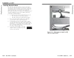
Safety Switch — Location only

The safety switch (figure 3-9) stops the downward motion of
platform when it encounters an obstruction to its smooth
operation.  If an obstruction is present that blocks the platform’s
travel, the stepper motor’s carriage lifts and activates the safety
switch.  The HSA’s motor logic automatically reverses the
platform’s motion and raises the platform to the upper position.
The carriage typically reverses with less than twelve pounds of
pressure applied to the obstruction.

Figure 3-9 shows the HSA with the shroud removed.

Safety
Switch

Stepper
Motor and
Carriage
Assembly

Figure 3-9 — Location of the safety switch
(seen from the side)

The safety switch cannot be adjusted.

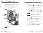
Replacing the Control Board Assembly and
Power Supply Assembly

The control board assembly (figure 3-1 on page 3-2, 

1

) and the

power supply assembly (

2

) can be replaced, if necessary, as

follows:

1

.

Disconnect AC power.

2

.

Remove the shroud.  See Removing and Replacing the
Shroud
, on page 3-6, step 1.

3

.

From the underside of the enclosure, reach into the cable
access holes (figure 3-1 on page 3-2, item 

3

), and cut the

tie wraps (

5

 shows the tie-downs) that route the AAP

cables and network (CAT 6) cables inside the enclosure.

4

.

Remove the three screws (figure 3-1 on page 3-2, item 

4

)

that secure the assembly to be replaced to the underside of
the enclosure.

For the control board assembly, screws indicated by an
asterisk (*) on figure 3-1 are accessible from the top
(inside the enclosure).

Do not remove screw 

X

 (figure 3-1 on page 3-2).

This screw does not secure the power supply assembly in
any way; rather, it provides structural support to the
enclosure.

5

.

Remove all connectors from the assembly to be replaced.

6

.

Remove the assembly from the enclosure.

7

.

Secure the replacement assembly in the enclosure with the
screws removed in step 4.

8

.

Reconnect all connectors removed in step 5.

9

.

Retie all of the network (CAT 6) and AAP cables removed
in step 3 to the tie-downs (figure 3-1 on page 3-2, item 

5

)

on the assembly that was replaced.

10

.

Reinstall the shroud.  See Removing and Replacing the
Shroud
, on page 3-6, step 3.

3-13

3-12

Содержание HSA 822MS

Страница 1: ...33 453 4040 Fax 31 33 453 4050 Extron Electronics Asia 135 Joo Seng Road 04 01 PM Industrial Building Singapore 368363 65 6383 4400 Fax 65 6383 4664 Extron Electronics Japan Kyodo Building 16 Ichibancho Chiyoda ku Tokyo 102 0082 Japan 81 3 3511 7655 Fax 81 3 3511 7656 www extron com 2005 Extron Electronics All rights reserved Motorized Hideaway Surface Access Enclosure 68 617 04 Rev Ax1 03 05 HSA ...

Страница 2: ...etrieb gesetzt werden Stromunterbrechung Um das Gerät auf sichere Weise vom Netz zu trennen sollten Sie alle Netzkabel aus der Rückseite des Gerätes aus der externen Stomversorgung falls dies möglich ist oder aus der Wandsteckdose ziehen Schutz des Netzkabels Netzkabel sollten stets so verlegt werden daß sie nicht im Weg liegen und niemand darauf treten kann oder Objekte darauf oder unmittelbar da...

Страница 3: ...ting the AAP Cables 2 16 Cabling the Enclosure 2 18 Cabling the RJ 45 connectors 2 19 Cabling the control and status connector 2 20 Bezels 2 23 Chapter 3 Maintenance and Modifications 3 1 Replacing an AAP 3 3 Replacing the Bezels 3 5 Removing and Replacing the Shroud 3 6 Setting the Upper Limit Switch Elevated Platform Height 3 7 Setting the Lower Limit Switch Lowered Platform Height 3 8 Setting t...

Страница 4: ... Enclosures Features 68 617 04 Rev Ax1 03 05 All trademarks mentioned in this manual are the properties of their respective owners Appendix A Reference Information A 1 Specifications A 2 Part Numbers A 4 HSA 822MS A 4 Included parts A 4 Template replacement parts and accessories A 4 Interface accessories A 5 Appendix B Packaging for Shipment B 1 ...

Страница 5: ...ss receptacles The motorized action is remotely controlled by contact closure The control mechanism uses discrete high or low signals to report the HSA s up or down position Safety devices prevent injury and equipment damage 1 2 The installed enclosure fits flush within a table or podium top storing the AAPs and connectors out of the way and out of sight To access the AAPs and connectors the user ...

Страница 6: ... OUTP UT LEVEL A B C D E PEAKIN G Projector Extron RGB 580xi SI AAP Interface on each side Extron HSA 822MS Surface Access Enclosure COMPUTER INPUT SELECT AUDIO Figure 1 2 HSA 822MS and RGB 580xi xi xi xi xi configuration Features Easy access to connectors and controls Durable motorized movement Motion limiting safety features to prevent injury and equipment damage A variety of colors of included ...

Страница 7: ...822MS Preliminary 2 Chapter Two Installation Installation Overview Preparing the Table Preparing the HSA Mounting the HSA Mounting the Table Surface Making Final Adjustments Cabling and Installing the AAPs Routing the AAP Cables Cabling the Enclosure Bezels 1 6 ...

Страница 8: ...Flexible Conduit Kit manual 3 Have a reputable carpenter or other craftsman cut a hole in the surface where the enclosure will be installed to the exact dimensions of the HSA Retain the removed piece of the table surface to form the top of the HSA See Preparing the Table on page 2 4 4 Run all cables necessary to support the AC control and status and RJ 45 connectors and all planned AAP connectors ...

Страница 9: ...f the same material that is the same size of the removed material for use as the top surface of the HSA For best results the surface block dimension should be 1 32 to 1 16 1 mm smaller on all four sides than the cutout hole The metal drilling template is reusable Do not discard this template when the installation is complete Save it for future HSA 822MS installations 1 Turn the table upside down C...

Страница 10: ...rews on each side of the panel do not fasten the panel in place They secure the AC power outlet 6 To ensure that you reinstall the RJ 45 connectors in the proper position when the installation is complete tag the internal CAT 6 cables to define their installation location such as top or bottom and side A or B Also tag the side of the enclosure itself A or B Remove panel Remove two screws ea side H...

Страница 11: ... finished surface 2 Measure and draw centerlines figure 2 8 at 3 21 8 15 cm or one half the length along the 6 42 16 31 cm length of the surface block 3 07 7 8 cm or one half the width along the 6 14 15 6 cm length of the surface block CAUTION It is crucial that you place the top plate over the surface block as closely centered as possible and that the long edge of the surface block is parallel to...

Страница 12: ...nector on the underside of the HSA use a piece of wire to temporarily jumper pin 4 to pin 5 to enable the manual activation press to activate operation of the HSA 2 With the unit unpowered gently press on the surface block to retract close the unit The surface block should fit snugly within the cut out hole If the surface block impacts the sides of the hole adjust the positioning of the HSA and th...

Страница 13: ...e lower limit switch set screw Clockwise to raise the stop point of the retracted platform Counterclockwise to lower the stop point of the retracted platform Adjustments do not take affect immediately You must use the motor mechanism to raise and lower the platform to see the affect of your adjustment e Plug in AC power Do not reach tools or your hands into the area behind the AC connectors or int...

Страница 14: ...o the HSA 822MS See appendix A Reference Information for RGB 580xi AAP part numbers The screws for installing an AAP are built into its AAP RJ 45 panel so no additional screws are needed Ensure that AC power is disconnected before servicing the HSA unit 1 Cable the rear of the AAPs before fastening the AAPs to the AAP RJ 45 panel Route the cables through the hole in the underside of the surface mo...

Страница 15: ...s as follows 1 Connect the enclosure to the appropriate power source 125 VAC 60 Hz 5 A US domestic version 220 240 V 50 60 Hz 5 A international versions 2 Press on the surface block to open the top panel and extend the AAP cables to their maximum pull 3 To prevent wear and tear or binding of the movement caused by cable movement secure the AAP cables inside the enclosure Use tie wraps to secure th...

Страница 16: ... marked with an asterisk are concealed by the removable tray Cabling the RJ 45 connectors Plug one end of a terminated CAT 5 or CAT 6 twisted pair TP cable into each of these RJ 45 female connectors Connect the other end to an appropriate telecommunications or data network device or to an Extron TP product An RJ 11 telephone plug can be connected to the RJ 45 jack The bottom RJ 45 connectors match...

Страница 17: ...n of the HSA s status pins 6 up 7 down and 9 power When a status condition is met the switch closes shorting the status pin to ground pulling it low When a status condition is not met the switch opens floating the status pin Status pins 6 7 and 9 can sink 5 VDC to 12 VDC 500 mA maximum V 2 1 1 W S STATUS PIN D N G HSA 822MS CTL BRD Figure 2 18 Equivalent status pin circuit Figure 2 19 expands upon...
Страница 18: ...the MLC 226 product manual The flex I O port on an Extron IP Link Ethernet Control Interface can be used in place of the MLC 226 and its digital input port Bezels The HSA 822MS ships with RJ 45 RJ 11 connector bezel plug ins in a variety of colors and a black blank bezel To change to a different color RJ 45 connector bezel or if an RJ 45 connector is not needed or desired replace the connector bez...

Страница 19: ...tions Replacing an AAP Replacing the Bezels Removing and Replacing the Shroud Setting the Upper Limit Switch Elevated Platform Height Setting the Lower Limit Switch Lowered Platform Height Setting the Manual Release Switch Safety Switch Location Only Replacing the Control Board Assembly and Power Supply Assembly 2 24 ...

Страница 20: ...tor 4 Assembly screws 9 Control and status connector 5 Cable tie downs X Structural screws Do not remove The screws indicated by a dagger on figure 3 1 are accessible from the top inside the enclosure Replacing an AAP Replace one or more AAPs as follows 1 Activate the motor to raise the platform and then disconnect the AC power Ensure that AC power is disconnected before servicing the HSA unit Whe...

Страница 21: ...ce 11 Replace the AAP RJ 45 panel in the surface mount enclosure and secure them in place with the screws removed in step 2 If you lose an AAP RJ 45 panel screw four spare screws are stored in the underside of the enclosure figure 3 1 on page 3 2 item 6 3 5 3 4 12 If you replaced an AAP cable to prevent wear and tear caused by cable movement secure the AAP cables underneath the table See Routing t...

Страница 22: ...t to the enclosure 2 Perform the desired maintenance procedure 3 7 3 6 3 Secure the two shroud halves to the enclosure frame with the eight screws per shroud half four per side removed in step 1 Orient the shroud halves such that the vertical column of center holes align with the column of screw inserts on the vertical slides Setting the Upper Limit Switch Elevated Platform Height This switch s po...

Страница 23: ...h the surrounding flange Set the retracted height of the platform as follows 1 Disconnect AC power 2 Remove the shroud See Removing and Replacing the Shroud on page 3 6 step 1 3 Locate the lower limit switch assembly figure 3 7 inside the enclosure Loosen the lower limit lock nut The lower limit switch looks similar to but not exactly like the upper limit switch shown on page 3 8 3 9 3 8 Lower Lim...

Страница 24: ...d the AC connectors or into the vicinity of the power supply 3 Locate the manual release switch assembly figure 3 8 inside the enclosure Manual Release Switch Assembly RJ 45 Connectors Manual Release Switch Manual Release Set Screw Lower Limit Set Screw Figure 3 8 Location of manual release switch assembly seen from the side The manual release switch looks similar to but not exactly like the upper...

Страница 25: ...s follows 1 Disconnect AC power 2 Remove the shroud See Removing and Replacing the Shroud on page 3 6 step 1 3 From the underside of the enclosure reach into the cable access holes figure 3 1 on page 3 2 item 3 and cut the tie wraps 5 shows the tie downs that route the AAP cables and network CAT 6 cables inside the enclosure 4 Remove the three screws figure 3 1 on page 3 2 item 4 that secure the a...

Страница 26: ...Maintenance and Modifications cont d HSA 822MS Maintenance and Modifications Preliminary HSA 822MS Preliminary A Appendix A Reference Information Specifications Part Numbers 3 16 ...

Страница 27: ...ximate dimensions CAUTION Allow only a reputable carpenter or craftsman to cut the hole in the furniture or other surface Pay special attention to the direction the unit will face the unit s AAP and connector access side is underlined Extron is not responsible for improperly cut mounting holes Top plate outer rim 9 54 W x 9 82 D 24 23 cm W x 24 94 cm D Top plate vertically lifting plate not includ...

Страница 28: ...g in inserts assorted colors and blank 10 pin captive screw connector 100 319 11 IEC power cord International models only Template replacement parts and accessories Part Part number HSA 822MS drilling template 70 xxx 01 HSA 822M MS power supply assembly 70 461 01 HSA 822M MS control board assembly 70 462 01 HSA 822 RJ 11 cable kit 70 226 01 HSA 822 flexible conduit adapter kit 70 228 01 Interface ...

Страница 29: ...HSA 822MS Reference Information Reference Information cont d Preliminary HSA 822MS Preliminary B Appendix B Packaging for Shipment A 8 ...

Страница 30: ... Support Hotline to obtain a return kit Extron will send the repair kit to the location you specify 2 Disconnect all cables remove any AAPs remove the HSA 822MS from the table or desk and remove the surface block as follows a Activate the motor to raise the platform and then disconnect the AC power Ensure that AC power is disconnected before servicing the HSA unit When AC power is removed the plat...

Страница 31: ...connect any cables from the rear of the existing AAPs From the underside of the enclosure reach into the cable access holes figure 3 1 on page 3 2 item 3 and cut the tie wraps 5 shows the tie downs that route the AAP cables inside the enclosure Carefully pull the cables through and out the bottom of the HSA f Remove the AAP s that you intend to keep from the AAP RJ 45 panels by unscrewing the nuts...

Страница 32: ...ews removed in step 2c If you lose an AAP RJ 45 panel screw four spare screws are stored in the underside of the enclosure figure 3 1 on page 3 2 item 6 l Disconnect the IEC power cord international versions only the RJ 45 connectors and the control and status connector figure 3 1 on page 3 2 items 7 8 and 9 from the connectors on the underside of the HSA m On the underside of the table support th...

Страница 33: ...ed tie wraps to secure the shipping restraints in place HSA 822MS Enclosure Yellow Shipping Restraint REPLACE Figure B 8 Installing the shipping restraints 4 Insert the HSA 822MS into one of the foam shells figure B 9 Either open end of the open top panel fits into the recesses in the foam Figure B 9 Installing the foam shell 5 Insert the opposite end of the HSA 822MS into the remaining foam shell...

Страница 34: ...ipment Preliminary Preliminary 6 Lower the foam protected HSA into the shipping carton figure B 11 Figure B 11 Placing the HSA in the shipping carton 7 Close the shipping carton and seal it with high quality shipping tape 8 Ship the HSA to Extron using a reputable shipping company B 10 B 11 ...

Страница 35: ...Packaging for Shipment Cont d HSA 822MS Packaging for Shipment Preliminary B 13 ...

Отзывы: