


Extron DTP HD DA 4K Series • Installation and Operation
7
for more information).
ATTENTION:
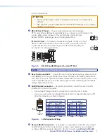
•
Do not connect these outputs to a telecommunications or computer data
network.
•
Ne connectez pas ces appareils à des données informatiques ou à un réseau
de télécommunications.
H
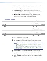
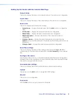
RS-232 Over TP port
— To pass bidirectional serial control between
DTP-compatible or HDBaseT-compatible devices, connect a control device to the
5-pole captive screw connector. This port includes only the 3 poles
labeled “RS-232” (see image below for wiring instructions).
IR Over TP port
— To transmit and receive IR signals, connect a control
device to the 5-pole captive screw connector. This port includes only the
2 poles labeled “IR” and shares the ground pole with the RS-232 port
(see figure 5 for wiring instructions).
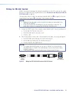
Tx/Rx
Pins
Rx
G
Tx
RS-232 IR
Rx
Tx
Tx
Rx
Rx
Tx
Gnd
Gnd
IR Device
RS-232 Device
Figure 5.
RS-232 and IR Wiring for the Over TP Port
NOTE:
RS-232 and IR data can be transmitted simultaneously.
I
Reset button and LED
— To reset the unit to factory default settings, press and hold
this
reset
button for approximately 9 seconds. The reset LED flashes green 3 times,
once every 3 seconds. After the third flash, release the button and quickly press it once
more to complete the reset. The LED flashes green 3 times indicating that the default
settings have been restored.
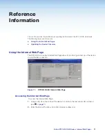
J
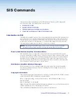
LAN (Ethernet) connector
— Use an RJ-45 cable to connect this jack to a LAN
(Ethernet) for control of the device.
•
Use a straight-through cable for connection to a switch, hub, or router.
•
Use a crossover cable or a straight-through cable for connection directly to a PC.
Wire the connector as shown in figure 6.
RJ-45
Connector
Insert Twisted
Pair Wires
Pins:
12345678
Straight-through Cable
(for connection to a switch, hub, or router)
End 1
End 2
Pin
Wire Color
Pin
Wire Color
1
white-orange
1
white-orange
2
orange
2 orange
3
white-green
3 white-green
4
blue
4 blue
5
white-blue
5 white-blue
6
green
6 green
7
white-brown
7 white-brown
8
brown
8 brown
Crossover Cable
(for direct connection to a PC)
End 1
End 2
Pin
Wire Color
Pin
Wire Color
1
white-orange
1 white-green
2
orange
2 green
3
white-green
3 white-orange
4
blue
4 blue
5
white-blue
5 white-blue
6
green
6 orange
7
white-brown
7 white-brown
8
brown
8 brown
T568B
T568A
T568B
TIA/EIA-T568B
Figure 6.
LAN Connector Wiring
K
Remote RS-232 connector
— (see Figure 4 on page 6) To control the unit, connect
an RS-232 device to this 3-pole, 3.5 mm captive screw connector and configure it
as follows: 9600 baud rate, 8 data bits,1 stop bit, no parity (see
Wiring for RS-232
IR
Tx Rx G
Tx Rx
RS-232
IR
Tx Rx G
Tx Rx
RS-232