background image


DMP 64 Plus • Dante Controller

25

Renaming a Receiver or Transmitter

In addition to renaming devices, individual receiver and transmitter channels can be 
renamed in Dante Controller. To better organize the various receivers and transmitters, 
it is recommended each receiver and each transmitter be named using a description of 
the device they belong to, the location of the device, or the purpose of the receiver or 
transmitter.

ATTENTION:

• 

It is essential that a Dante device be named before audio subscriptions with other 
devices are established. Existing subscriptions are removed when a device is 
renamed.

• 

Il est essentiel qu’un appareil Dante soit nommé avant l’établissement des 
abonnements audio avec d’autres appareils. Les abonnements existants sont 
supprimés lorsqu’un appareil est renommé.

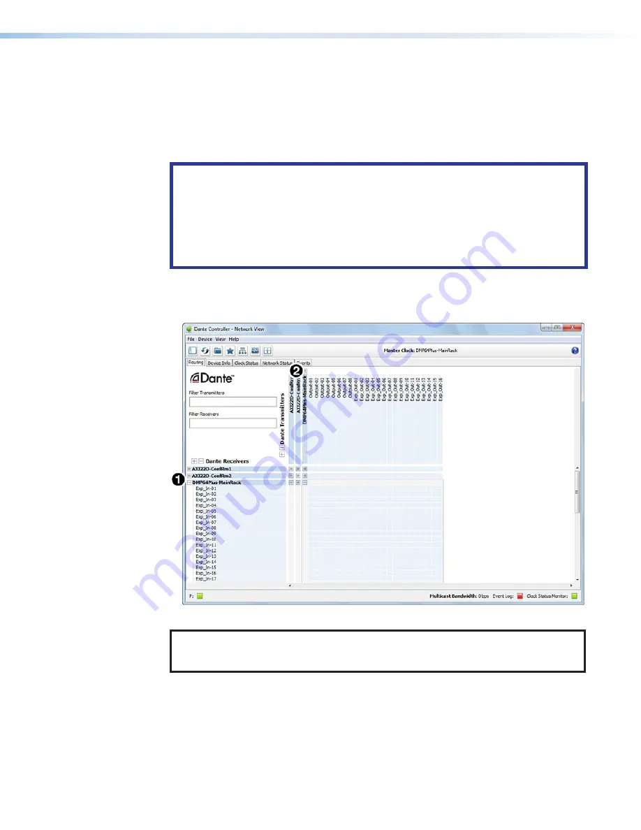
To view the receiver or transmitter channels in Dante Controller, click the 

+

 sign next to the 

receiver or transmitter device name to expand it. The 

+

 sign becomes a 

 sign when the 

device is expanded (see figure 30

1

).

Figure 30. 

Expanded Device View — Input and Output Names

TIP:


To simplify setup and operation of large matrix systems, rename the receiver and 

transmitter channels to better indicate the source at the transmitters or 
receivers.

Renaming a Receiver or Transmitter

The default names shown in the 

Dante Receivers

 column are extracted from the Dante 

interface of the connected device (

1

 and 

2

). The DMP 64 Plus receivers are labelled 

EXP_In-01

 through 

EXP_In-48

 because the DMP 64 Plus can receive signal at the 48 EXP 

inputs. Follow the instructions on the next page to rename a receiver or transmitter.

30 

Содержание DMP 64 Plus

Страница 1: ...User Guide DMP 64 Plus Audio Products Mixers and Processors ProDSP Digital Matrix Processor 68 3291 01 Rev C 10 22 ...

Страница 2: ...his symbol when used on the product is intended to alert the user of important operating and maintenance servicing instructions in the literature provided with the equipment For information on safety guidelines regulatory compliances EMI EMF compatibility accessibility and related topics see the Extron Safety and Regulatory Compliance Guide part number 68 290 01 on the Extron website www extron co...

Страница 3: ...PoleVault PowerCage PURE3 Quantum ShareLink Show Me SoundField SpeedMount SpeedSwitch StudioStation System INTEGRATOR TeamWork TouchLink V Lock VN Matrix VoiceLift WallVault WindoWall XPA XTP XTP Systems and ZipClip Registered Service Mark SM S3 Service Support Solutions Trademarks AAP AFL Accu RATE Frame Lock ADSP Advanced Digital Sync Processing AVEdge CableCover CDRS Class D Ripple Suppression ...

Страница 4: ...es torsadées fonctionne avec les câbles paires torsadées blindées UTP ou non blindées STP Afin de s assurer de la compatibilité entre FCC Classe A et CE les câbles STP et les connecteurs STP sont nécessaires NOTES This unit was tested with shielded I O cables on the peripheral devices Shielded cables must be used to ensure compliance with FCC emissions limits For more information on safety guideli...

Страница 5: ...r or device responses used in this guide the character 0 is used for the number zero and O is the capital letter o Computer responses and directory paths that do not have variables are written in the font shown here Reply from 208 132 180 48 bytes 32 times 2ms TTL 32 C Program Files Extron Variables are written in slanted form as shown here ping xxx xxx xxx xxx t SOH R Data STX Command ETB ETX Sel...

Страница 6: ... Panel 18 Live and Emulate Panel 19 Dante Controller 21 Overview 21 Downloading and Installing Dante Controller 21 Configuring the DMP 64 Plus in Dante Controller 22 Device Name 22 Receiver and Transmitter Names 22 Dante Controller Naming Conventions 23 Renaming the DMP 64 Plus in Dante Controller 23 Renaming a Receiver or Transmitter 25 Finding a Dante Device IP Address 26 Physical Dante Network ...

Страница 7: ... Symbol Definitions 38 Command and Response Table for SIS Commands 44 Command and Response Table for DSP SIS Commands 54 Command and Response Table for VoIP SIS Commands 59 Object ID OID Number Tables 61 Input Path OIDs 61 Output Path OIDs 63 Automixer OIDs 64 Mix point OIDs 66 Internal Web Pages 74 Accessing the Embedded Web Pages 74 DMP 64 Plus Default Web Page 75 Communication Settings 75 RS 23...

Страница 8: ...Audio Matrix Processor is a 6x4 audio mixer with broad I O expansion capabilities including 8 auxiliary inputs via VoIP V models only USB and internal audio files 16x16 expansion bus Dante 32x16 AT channels AT models only VoIP V models only Digital I O The DMP 64 Plus features Extron ProDSP automixing AEC Acoustic Echo Cancellation and USB audio for use as an audio to PC interface The DMP 64 Plus ...

Страница 9: ...ude up to eight VoIP lines that support generic Session Initiation Protocol SIP 2 0 connectivity per RFC 3261 The DMP 64 Plus V models are compatible with select VoIP systems and can be used for a single VoIP line or as a VoIP farm for up to eight rooms Compact half rack size FlexInput capability on main inputs AT models only All six main inputs offer FlexInput capability to select a Dante channel...

Страница 10: ...tely 20 minutes of playback time and saved to the onboard storage Low latency Powerful DSP chips maximize performance resulting in latency that is very low from input to output regardless of the number of active channels or processes While latency increases in channels with AEC enabled and marginally with the automixer overall latency remains low This keeps audio in sync with video and prevents di...

Страница 11: ... ACP REMOTE USB AUD LAN VoIP R 1 2 C V AT 1 PRI PoE 2 SEC RS 232 Tx V IN G O IN G O IN G O IN G O IN G O IN G O S S Rx G G 1 2 3 4 5 6 1 2 3 4 POWER 12V 2 0A MAX 1 2 3 4 5 6 A B C D E F G H I J K A Power input E RS 232 port I Mic Line inputs B EXP port F LAN ports J Digital I O ports C AT ports AT models only G USB Audio port K Line outputs D ACP port H Reset button and LED Figure 2 Rear Panel Fea...

Страница 12: ...Plus rear panel ACP port provides 6 W of power Use an Extron PS 1220EB power supply or Extron 12 V desktop power supply when additional power is required Refer to the applicable Audio Control Panel ACP setup guides available at www extron com for wiring details G S S V Ground Signal Signal 12 VDC Black and Drains Green White Red G S S V Drain Wires Basic ACP Connector Wiring Figure 3 ACP Port Conn...

Страница 13: ...on downloading Toolbelt and the Toolbelt Help File for device configuration G USB Audio port see figure 2 on page 4 Connect a Windows or Mac computer to this USB mini B port to interface with the DMP 64 Plus as a USB audio device see Configure USB Audio on page 17 for details on configuring the USB audio Audio sample rate is 48 kHz 16 bit H Reset button and LED Initiates three levels of resets 1 4...

Страница 14: ...s 6 pole Captive Screw Connector 1 2 G IN O G IN O Figure 6 Digital I O Connector The Digital Input and Output ports function by reacting to either HIGH or LOW logic based on applied voltages Digital Input If the input voltage is lower than 0 8 V it is considered logic LOW If the input voltage is greater than 3 0 V it is logic HIGH The maximum input voltage is 12 0 VDC Digital Output The output po...

Страница 15: ...cted to a second EXP device and is configured as the primary unit Blinking The unit is connected to a second EXP device and is configured as the secondary unit EXP Indicator LEDs AT Models On The unit is connected to a second EXP non AT device and is configured as the primary unit Blinking The unit is not connected to a second device USB Activity Indicator LED Blinks to indicate audio streaming ov...

Страница 16: ...entation externe SECTION A A Ridges Smooth A A 3 16 5 mm Max POWER 12V 2 0A MAX Figure 9 Power Input Wiring 1 Cut the DC output cord to the length needed 2 Strip the jacket to expose 3 16 inches 5 mm of the conductor wire see figure 9 3 Ensure the connections have the correct polarity as shown in the figure above The wire with ridges is the ground wire 4 Slide the exposed ends of the wire into the...

Страница 17: ...re not suitable for use in air handling spaces or in wall cavities Sauf mention contraire les adaptateurs AC DC ne sont pas appropriés pour une utilisation dans les espaces d aération ou dans les cavités murales The installation must always be in accordance with the applicable provisions of National Electrical Code ANSI NFPA 70 article 725 and the Canadian Electrical Code part 1 section 16 The pow...

Страница 18: ...le for connection to a switch hub or router End 1 End 2 Pin Wire Color Pin Wire Color 1 white orange 1 white orange 2 orange 2 orange 3 white green 3 white green 4 blue 4 blue 5 white blue 5 white blue 6 green 6 green 7 white brown 7 white brown 8 brown 8 brown Crossover Cable for direct connection to a PC End 1 End 2 Pin Wire Color Pin Wire Color 1 white orange 1 white green 2 orange 2 green 3 wh...

Страница 19: ...dress for LAN 1 and LAN 2 V models only 255 255 255 0 Gateway IP address for LAN 1 and LAN 2 V models only 0 0 0 0 Enable ARP capability Turns off DHCP for LAN 1 and LAN 2 V models only Use mode 4 to reset all IP settings back to factory defaults Reset to Factory Defaults 5 Hold in the Reset button until reset LEDs blink three times once at 3 seconds again at 6 seconds again at 9 seconds Then rele...

Страница 20: ...tron com to download and install the DSP software NOTES Download the latest versions of software and firmware for your product An Extron Insider account is required to download and use the firmware or software 1 Mouse over the Download tab see figure 11 1 at the top of the page Figure 11 Software Links on Download Screen 2 Click the appropriate link on the drop down list The Download Center page o...

Страница 21: ...software firmware update Figure 13 DSP Configurator Software For firmware NOTE Firmware will only be listed if your device has a firmware update Figure 14 DMP Plus Firmware 6 Install the software a Navigate to the folder where the software file was downloaded b Double click the executable file and follow the on screen directions to install the software For firmware a To install via internal web pa...

Страница 22: ...ner of any dialog box in DSP Configurator Alternatively click Help Contents in the menu bar at the top of the main workspace or press F1 on your keyboard This help file contains detailed procedures and further instruction on all DSP Configurator features DSP Configurator Main Workspace NOTE For details about specific software features and device configurations refer to the DSP Configurator Help Fi...

Страница 23: ...Device Conversion dialog opens Edit The Edit menu offers the standard Windows Edit Menu options such as Cut Copy and Paste View Meter Bridge Opens a meter bridge to view input and output activity The meter bridge is a floating window allowing use of the DSP Configurator workspace while simultaneously monitoring input and output activity NOTE The meter bridge is only available in Live mode with a T...

Страница 24: ...figure Macros dialog box for creating editing and deleting macro functions Configure USB Audio Opens the Configure USB Control dialog with Windows communication volume and mute controls and Windows playback volume and mute controls to affect levels and mute status in the connected Extron USB audio processor Configure Internal Triggers Opens the Internal Trigger Setup dialog with the configuration ...

Страница 25: ...cros that have been pushed to the device can be run from the Run Macro drop down list Figure 19 Macros Presets Drop Down List Select the Presets drop down list see figure 20 to view and apply presets saved in the current configuration file or on a device connected in Live mode Presets with an asterisk next to them are on the DMP 64 Plus but not in the current configuration file Run a preset to loa...

Страница 26: ... Live button in the menu bar of the DSP Configurator Alternatively select Tools Connect to Device or press F6 on the keyboard The Connect to device dialog box opens see figure 22 2 Connect to the DMP 64 Plus To connect via TCP IP A Click the TCP IP tab in the dialog box Enter the IP address of the device in the Hostname or IP Address field If necessary enter the device password in the Password fie...

Страница 27: ...anel and the device is ready for further configuration Exit Live Mode and Enter Emulate Mode 1 Click the Emulate button in the DSP Configurator menu bar Alternatively select Tools Disconnect from Device or press F6 on the keyboard 2 Click OK to confirm Emulate Mode While in Emulate mode DSP Configurator is functioning in an offline state Changes made to the configuration file are not applied to a ...

Страница 28: ...ted onto the Dante network Audinate recommends the Dante audio network be kept separate from other networks However the audio network can be shared with control traffic or unrelated data traffic Audio channels can be unicast or multicast to make the best use of available bandwidth Downloading and Installing Dante Controller Dante Controller from Audinate is required to route transmitters and recei...

Страница 29: ...t device name of the DMP 64 Plus consists of the model name followed by the last six characters of the Dante interface MAC address for example DMP64P 0ee8ee In addition to renaming the device individual Transmitter Tx and Receiver Rx channels can be renamed The Dante device name must be set before making any connections to other devices on the Dante network Renaming a device after making connectio...

Страница 30: ... Plus are connected to the same network 2 From the control computer Start menu select All Programs Audinate Dante Controller Dante Controller 3 The Dante Controller Network View screen opens All Dante devices on the network are discovered and listed 4 From the Device menu select Device View or press Ctrl D on the keyboard see figure 25 5 The Dante Controller Device View dialog opens Select the dev...

Страница 31: ...o spaces are allowed in the name Names should be significant identifiers For example enter DMP64Plus MainRack 2 8 Click Apply 3 A confirmation prompt opens 9 Click Yes see figure 29 1 to confirm the new name then close the Device Configuration dialog box The new name is written to the Dante interface of the DMP 64 Plus Repeat as necessary for all devices NOTE The device name assigned in Dante Cont...

Страница 32: ...vec d autres appareils Les abonnements existants sont supprimés lorsqu un appareil est renommé To view the receiver or transmitter channels in Dante Controller click the sign next to the receiver or transmitter device name to expand it The sign becomes a sign when the device is expanded see figure 30 1 Figure 30 Expanded Device View Input and Output Names TIP To simplify setup and operation of lar...

Страница 33: ...text box 7 Repeat steps 4 through 6 to rename additional receiver or transmitter channels 8 When finished renaming receivers and transmitter close the Device View dialog box Finding a Dante Device IP Address To find the IP address of a Dante device the name of the device is needed see Renaming the DMP 64 Plus in Dante Controller on page 23 NOTE If the DMP 64 Plus has not been renamed its default n...

Страница 34: ...2 C V AT 1 PRI PoE 2 SEC RS 232 Tx V IN G O IN G O IN G O IN G O IN G O IN G O S S Rx G G 1 2 3 4 5 6 1 2 3 4 POWER 12V 2 0A MAX 1 2 3 4 5 6 Ethernet Figure 33 Daisy Chain Network Topology NOTE The daisy chain topology only functions in switched mode It is not possible to use in redundant mode Redundant Configuration In redundant mode the 2 port AT switch see figure 2 C on page 4 becomes separate ...

Страница 35: ...es The DMP 64 Plus transmitters and receivers are available in Dante Controller for routing to other Dante devices Routing Devices After the DMP 64 Plus is configured the channels can be routed to the other Dante devices on the audio network Channels transmitted to the network or received from the network are routed using the Dante Controller Routing tab on the Network View page see figure 34 on p...

Страница 36: ...Click the intersection of the desired subscription between a transmitter and a receiver 3 A check mark at the intersection indicates the subscription is made A check mark also appears next to the receiver channel NOTE A receiver can connect to only one transmitter A transmitter can connect to multiple receivers Figure 35 Routing Tab of Network Screen Disconnecting Inputs from Outputs To undo routi...

Страница 37: ...step 4 see Enable remote connection for listening on page 52 Repeat if necessary for all desired devices Example Command Response wcAXI02 XTP RoomA 1expr ExprCAXI XTP RoomA 1 NOTE AXI devices can be set up for listening even if not currently connected to the DMP unit 8 To verify that the DMP is listening to the correct remote devices use the Query remote devices being listened to command to displa...

Страница 38: ...p down list 1 4 Click the Reboot button 2 to reboot the device and enable AES67 To create an AES67 Multicast Flow Figure 36 AES67 Mode 1 Open Dante Controller and double click the Dante device name in the Routing tab to open Device View 2 Click the Create a new multicast flow button 3 In the Flow Config section click the AES67 radio button 4 In the Flow Config section select Auto or Manual Destina...

Страница 39: ...o diagnose the PC network connections as described below Check Dante Controller after each step to see if the problem is resolved 1 Click the Choose a Dante Interface icon see figure 37 1 The Configure Dante Interfaces dialog box opens see figure 38 Figure 37 Choose a Dante Interface Icon Be certain the correct LAN connection is selected the PC LAN port that is physically connected to the AT netwo...

Страница 40: ...ware To access the Dante Controller Help file do any of the following Figure 39 Accessing the Dante Help File Click the Help icon in the upper right corner of the Network View screen see figure 39 1 Select Help then Online Help or Offline Help from the menu 2 Press the F1 key on the computer keyboard for online help or Shift F1 for offline help ...

Страница 41: ...d No parity 1 stop bit 8 data bits No flow control NOTE The rear panel configuration port requires 38400 baud communication This speed is higher than most other Extron products The DMP 64 Plus control software automatically sets the connection for the appropriate speed When using DataViewer or similar application make sure the host PC or control system is set for 38400 baud Front Panel Configurati...

Страница 42: ...not changed the value the factory specified default 192 168 254 254 is the correct value for this field 2 The device responds with a copyright message including the date the name of the product firmware version part number and the current date time 3 If the device is password protected enter the appropriate administrator or user password a If the password is accepted the device responds with Login...

Страница 43: ...racters per field No special characters are required to begin or end a command character sequence When a command is valid the transmitter executes the command and sends a response to the host device All responses from the transmitter to the host end with a carriage return and a line feed CR LF which signals the end of the response character string A string is one or more characters Device Initiate...

Страница 44: ...ghout the SIS tables to represent variables in the command response fields Command and response examples are shown throughout the table The ASCII to HEX conversion table see figure 40 is for use with the command and response tables ASCII to Hex Conversion Table Space Figure 40 ASCII to Hex Conversion Table NOTE For commands and examples of computer or device responses used in this guide the charac...

Страница 45: ...cters space OK for names Symbol Definitions Common Symbol Definitions CR LF carriage return line feed hex 0D 0A or Carriage return or pipe symbol no line feed hex 0D E Escape key or hex 1B use W instead of E for web browsers or at any time Pipe vertical bar character URL equivalent to carriage return Space Asterisk character which is a command character not a variable NOTES If unit does not suppor...

Страница 46: ...N none default X1 Data Pacing Specified in milliseconds between bytes 0000 1000 ms default is 0 ms For host port or ports this value is ignored and always returns a 0 X1 Password 0 128 characters All human readable characters are permitted except Password cannot be a single space Passwords are case sensitive X1 Reading Password Responds with 4 asterisks if password exists and empty if not instead ...

Страница 47: ...rding to the action type Mutes Input number for muting If X3 is not specified muting matches the input with the corresponding I O channel number Group Mutes Group member for muting If X3 is not specified muting matches the group with the corresponding I O channel number Macros Macro number If X3 is not specified the macro number defaults to the corresponding I O channel number Presets Preset numbe...

Страница 48: ...h 16 inputs 9 16 are Aux outputs 1 8 X4 EXP Output Number 1 through 16 X4 Name Invalid characters and X4 Audio File Name Valid characters are A Z a z 0 9 _ X4 Player ID 1 through 8 X4 Play State 0 Stopped 1 Playing X4 Macro Number 1 through 64 Response will be padded with a leading 0 X4 Macro Status 0 Macro idle 1 32 Macro step X5 Macro Name 24 characters maximum A Z a z 0 9 _ X5 SNMP Access 0 Dis...

Страница 49: ...3 12 USB 2 Rx Right Channel 21 VoIP Line 5 Rx 4 File Tone Playback Player 4 13 USB 3 Rx Left Channel 22 VoIP Line 6 Rx 5 File Tone Playback Player 5 14 USB 3 Rx Right Channel 23 VoIP Line 7 Rx 6 File Tone Playback Player 6 15 USB 4 Rx Left Channel 24 VoIP Line 8 Rx 7 File Tone Playback Player 7 16 USB 4 Rx Right Channel 8 File Tone Playback Player 8 17 VoIP Line 1 Rx X7 Update Status 0 Disabled 1 ...

Страница 50: ...atus 0 Unregistered 2 Registered to 2nd proxy 4 Not registered failed 1 Registered to 1st proxy 3 None X9 Call Status 0 None 2 Active 4 Incoming 1 Inactive 3 On Hold 5 Outgoing X9 Duration HH MM SS X9 Codec name X9 Jitter in milliseconds X9 Packet drop count X9 Total packet count X9 Extension Number Valid characters are 0 9 X9 Hold Status 0 Off 1 On hold X9 Repeat Status 0 Play once 1 Repeat X9 Ta...

Страница 51: ...urrent connected port timeout E0 X2 TC Pti0 X2 View current connected port timeout E0TC X2 Set global IP port timeout E1 X2 TC Pti1 X2 View global IP port timeout E1TC X2 KEY X2 IP Timeout The number of seconds before timeout on IP connections min 1 max 65000 and default 30 300 seconds If no data is received during the timeout period the Ethernet connection will be closed Each step 10 seconds Seri...

Страница 52: ...subnet mask and the second X represents the gateway IP address View IP subnet gateway all EX2 CISG X X2 X Set DNS server IP address EX DI Ipd X View DNS server IP address EDI X KEY X GMT Offset Value This represents hours and minutes hh mm offset from Greenwich Mean Time X Unit Name Text string up to 63 characters drawn from the alphabet A Z digits 0 9 and minus sign hyphen X Local Date and Time F...

Страница 53: ... removes the password KEY X1 Password 0 128 characters All human readable characters are permitted except Password cannot be a single space Passwords are case sensitive X1 Reading Password Responds with 4 asterisks if password exists and empty if not instead of actual password X2 Connection Security Level 11 User 12 Administrator Directories Change create directory Epath directory CJ Dir path dire...

Страница 54: ...ort map EX5 MT PmtX5 LAN 1 only Reset telnet port map E23MT Pmt00023 LAN 1 only Disable telnet port E0MT Pmt00000 LAN 1 only View telnet port map EMT X5 LAN 1 only Set web port map EX5 MH PmhX5 LAN 1 only Reset web port map E80MH Pmt00080 LAN 1 only Disable web port map E0MH Pmt00000 LAN 1 only View web port map EMH X5 LAN 1 only Set telnet port map EZX5 X5 PMAP PmapZ X5 X5 Reset telnet port map E...

Страница 55: ...iew SSL port map ESX5 PMAP X5 KEY X5 Ethernet Port Number 0 Off custom port numbers must be 1024 or higher X5 Network Interface Card 1 LAN 1 2 LAN 2 SNMP Simple Network Management Protocol Set unit contact ECX3 SNMP SnmpC X3 Set unit contact to default EC SNMP SnmpC Not Specified View unit contact ECSNMP X3 Set unit location ELX3 SNMP SnmpL X3 Set unit location to default EL SNMP SnmpL Not Specifi...

Страница 56: ...l number Macros Macro number If X3 is not specified the macro number defaults to the corresponding I O channel number Presets Preset number If X3 is not provided the preset number defaults to the corresponding I O channel number X3 Digital Output 1 X3 Output Mode 0 Output always high 1 Output always low Mutes 2 Mute high 3 Unmute high Group Mutes 4 Group mute high 5 Group unmute high Macros 6 Macr...

Страница 57: ... Write output name EX4 X4 NO NmoX4 X4 Write EXP output name EX4 X4 NX NexX4 X4 Write preset name EX3 X4 NG NmgX3 X4 KEY X3 Preset number 1 through 32 X3 Input number 1 through 20 inputs 13 20 are Aux inputs 1 8 X4 Virtual return number 1 through 16 X4 EXP input number 1 through 16 X4 Output number 1 through 16 outputs 9 through 16 Aux inputs 1 8 X4 EXP output number 1 through 16 X4 Name Invalid ch...

Страница 58: ...eserve communication with the device KEY X3 Preset number 1 through 32 Player File Management Set file to slot association EAX4 X4 CPLY CplyAX4 X4 Clear file to slot association EAX4 CPLY CplyAX4 View file to slot association EAX4 CPLY X4 KEY X4 Audio file name Valid characters are A Z a z 0 9 _ X4 Player ID 1 through 8 Player Commands Start playback on a specific player EX4 1PLAY PlayX4 1 Stop pl...

Страница 59: ...n The following commands configure the DMP 64 Plus to listen for and pass through SIS commands meant for Extron endpoints controlled over Dante such as AXI AT or NetPA Ultra AT devices NOTE The DMP must be set to Verbose mode 1 3 when using the Dante Control and Configuration commands Query available remote devices EAEXPR Verbose Mode 2 3 X X ExprA X X Enable remote connection for listening ECX X2...

Страница 60: ... SIS Configuration and Control 53 Command ASCII command host to device Response device to host Additional description USB Call Status View USB 1 call status EH1UPHN UphnH1 X9 KEY X9 Call status 0 Inactive 1 Active ...

Страница 61: ...s All responses are shown with the DMP 64 in Verbose mode 2 or 3 Set gain level EGX5 X5 AU DsGX5 X5 Set gain on OID X5 to a value of X5 dB Example 1 mic line input 1 EG40000 120AU DsG40000 120 Set the mic line input 1 to a level of 12 0 dB Example 2 pre mixer gain 1 EG40100 8AU DsG40100 8 Set pre mixer gain 1 to a value of 0 8 dB Read gain level EGX5 AU DsGX5 X5 Gain on OID X5 is set to a value of...

Страница 62: ...ecrease the level of the X6 group fader by X6 dB View the group fader value EDX6 GRPM GrpmDX6 X6 In verbose modes 0 and 1 the response is simplified to X6 Mute a group EDX6 1GRPM GrpmDX6 1 Mute all blocks in group X6 Unmute a group EDX6 0GRPM GrpmDX6 0 Unmute all blocks in group X6 View a group mute value EDX6 GRPM GrpmDX6 X6 For group masters X6 is always expressed as an unsigned or negative valu...

Страница 63: ... meter response rate ERX6 GRPU GrpuRX6 View global unsolicited meter response rate ERGRPU Verbose Mode 2 3 X6 GrpuRX6 Set unsolicited meter group EGX6 GRPU GrpuGX6 View unsolicited meter group EGGRPU Verbose Mode 2 3 X6 GrpuGX6 View OID members in meter group EOX6 GRPM GrpmOX6 OID 1 OID 2 OID n This returns the group number followed by the list of OIDs Enable meters in meter group EDX6 1GRPM GrpmD...

Страница 64: ...Channel 24 VoIP Line 8 Rx 7 File Tone Playback Player 7 16 USB 4 Rx Right Channel 8 File Tone Playback Player 8 17 VoIP Line 1 Rx Aux Output 1 through 8 Set output mode EDX5 X7 AU DsDX5 X7 Get output mode EDX5 AU X7 Set mute EMX5 X6 AU DsMX5 X6 Get mute status EMX5 AU X6 Set attenuation EGX5 X5 AU DsGX5 X5 Read attenuation level EGX5 AU X5 KEY X5 Target OID See Object ID OID Number Tables on page ...

Страница 65: ...e closed 1024 gate opened X9 Target OID See Automixer OIDs on page 64 Signal Level Monitoring SLM SLM tracks when the signal at a metered gain OID crosses a set threshold level When SLM is enabled for an OID an unsolicited message is sent when the threshold level is crossed The response includes the OID meter on off status level after the threshold was crossed and if the level was going up or down...

Страница 66: ...HOLDX8 X8 X9 VOIP VoipHOLDX8 X8 X9 X8 Transfer EXFERX8 X8 X8 VOIP VoipXFERX8 X8 X8 KEY X8 Line number 1 through 8 X8 Appearance number 1 through 8 where 1 is the originating two party call X8 Phone number No spaces allowed Valid characters are 0 9 X8 Return code 0 Ok 1 Fail X9 Hold status 0 Off 1 On hold Call Settings Set do not disturb EDNDX8 X8 VOIP VoipDNDX8 X8 Get do not disturb status EDNDX8 ...

Страница 67: ...1 Inactive 3 On hold 5 Outgoing Line Status Queries get only Registration status ERSX8 VOIP VoipRSX8 X8 Line status ELSX8 X8 VOIP VoipLSX8 X8 X9 Line status without index ELSX8 VOIP VoipLSX8 X9 X9 X9 X9 X9 X9 X9 X9 Each X9 entry represents an appearance of the line Caller name ENAMEX8 X8 VOIP VoipNAMEX8 X8 X8 X9 Duration EDURX8 X8 VOIP VoipDURX8 X8 X9 Codec ECDX8 X8 VOIP VoipCDX8 X8 X9 Jitter Rx E...

Страница 68: ... Input Pre mixer Gain Block OID Aux Input 1 40012 Aux Input 1 40112 Aux Input 2 40013 Aux Input 2 40113 Aux Input 3 40014 Aux Input 3 40114 Aux Input 4 40015 Aux Input 4 40115 Aux Input 5 40016 Aux Input 5 40116 Aux Input 6 40017 Aux Input 6 40117 Aux Input 7 40018 Aux Input 7 40118 Aux Input 8 40019 Aux Input 8 40119 Virtual Return Pre mixer Gain Block OID Virtual Return Pre mixer Gain Block OID ...

Страница 69: ...0208 EXP 1 50232 AT In 10 EXP 10 50209 EXP 2 50233 AT In 11 EXP 11 50210 EXP 3 50234 AT In 12 EXP 12 50211 EXP 4 50235 AT In 13 EXP 13 50212 EXP 5 50236 AT In 14 EXP 14 50213 EXP 6 50237 AT In 15 EXP 15 50214 EXP 7 50238 AT In 16 EXP 16 50215 EXP 8 50239 AT In 17 50216 EXP 9 50240 AT In 18 50217 EXP 10 50241 AT In 19 50218 EXP 11 50242 AT In 20 50219 EXP 12 50243 AT In 21 50220 EXP 13 50244 AT In ...

Страница 70: ...tput 7 60014 Aux Output 8 60115 Aux Output 8 60015 EXP Output Post mixer Trim Block OID EXP Output Post mixer Trim Block OID EXP Output 1 60116 EXP Output 9 60124 EXP Output 2 60117 EXP Output 10 60125 EXP Output 3 60118 EXP Output 11 60126 EXP Output 4 60119 EXP Output 12 60127 EXP Output 5 60120 EXP Output 13 60128 EXP Output 6 60121 EXP Output 14 60129 EXP Output 7 60122 EXP Output 15 60130 EXP...

Страница 71: ...x Automixer 2 59013 Aux Automixer 6 59017 Aux Automixer 3 59014 Aux Automixer 7 59018 Aux Automixer 4 59015 Aux Automixer 8 59019 Expansion Bus Automixer OID OID Expansion Bus Automixer OID OID Automixer 1 59020 Automixer 9 59028 Automixer 2 59021 Automixer 10 59029 Automixer 3 59022 Automixer 11 59030 Automixer 4 59023 Automixer 12 59031 Automixer 5 59024 Automixer 13 59032 Automixer 6 59025 Auto...

Страница 72: ...OID Automixer 33 59052 Automixer 41 59060 Automixer 34 59053 Automixer 42 59061 Automixer 35 59054 Automixer 43 59062 Automixer 36 59055 Automixer 44 59063 Automixer 37 59056 Automixer 45 59064 Automixer 38 59057 Automixer 46 59065 Automixer 39 59058 Automixer 47 59066 Automixer 40 59059 Automixer 48 59067 ...

Страница 73: ...5 20432 20433 20434 20435 20436 20437 20438 20439 20440 20441 20442 20443 20444 20445 20446 20447 Mic 6 20532 20533 20534 20535 20536 20537 20538 20539 20540 20541 20542 20543 20544 20545 20546 20547 Mic Line Input to Virtual Send Mix Matrix A B C D E F G H I J K L M N O P Mic 1 20016 20017 20018 20019 20020 20021 20022 20023 20024 20025 20026 20027 20028 20029 20030 20031 Mic 2 20116 20117 20118 ...

Страница 74: ...0 21621 21622 21623 21624 21625 21626 21627 21628 21629 21630 21631 Aux 6 21716 21717 21718 21719 21720 21721 21722 21723 21724 21725 21726 21727 21728 21729 21730 21731 Aux 7 21816 21817 21818 21819 21820 21821 21822 21823 21824 21825 21826 21827 21828 21829 21830 21831 Aux 8 21916 21917 21918 21919 21920 21921 21922 21923 21924 21925 21926 21927 21928 21929 21930 21931 Virtual Return to Analog a...

Страница 75: ...433 23434 23435 23436 23437 23438 23439 23440 23441 23442 23443 23444 23445 23446 23447 Rtn P 23532 23533 23534 23535 23536 23537 23538 23539 23540 23541 23542 23543 23544 23545 23546 23547 Virtual Return to Virtual Send Mix Matrix A B C D E F G H I J K L M N O P Rtn A 22016 22017 22018 22019 22020 22021 22022 22023 22024 22025 22026 22027 22028 22029 22030 22031 Rtn B 22116 22117 22118 22119 2212...

Страница 76: ...24902 24903 24908 24909 24910 24911 24912 24913 24914 24915 Exp 15 25000 25001 25002 25003 25008 25009 25010 25011 25012 25013 25014 25015 Exp 16 25100 25101 25102 25103 25108 25109 25110 25111 25112 25113 25114 25115 Out 1 Out 2 Out 3 Out 4 Aux Out 1 Aux Out 2 Aux Out 3 Aux Out 4 Aux Out 5 Aux Out 6 Aux Out 7 Aux Out 8 Exp 17 25200 25201 25202 25203 25208 25209 25210 25211 25212 25213 25214 25215...

Страница 77: ...ut 1 EXP Out 2 EXP Out 3 EXP Out 4 EXP Out 5 EXP Out 6 EXP Out 7 EXP Out 8 EXP Out 9 EXP Out 10 EXP Out 11 EXP Out 12 EXP Out 13 EXP Out 14 EXP Out 15 EXP Out 16 Exp 1 23632 23633 23634 23635 23636 23637 23638 23639 23640 23641 23642 23643 23644 23645 23646 23647 Exp 2 23732 23733 23734 23735 23736 23737 23738 23739 23740 23741 23742 23743 23744 23745 23746 23747 Exp 3 23832 23833 23834 23835 2383...

Страница 78: ...44 26645 26646 26647 Exp 32 26732 26733 26734 26735 26736 26737 26738 26739 26740 26741 26742 26743 26744 26745 26746 26747 EXP Out 1 EXP Out 2 EXP Out 3 EXP Out 4 EXP Out 5 EXP Out 6 EXP Out 7 EXP Out 8 EXP Out 9 EXP Out 10 EXP Out 11 EXP Out 12 EXP Out 13 EXP Out 14 EXP Out 15 EXP Out 16 Exp 33 26832 26833 26834 26835 26836 26837 26838 26839 26840 26841 26842 26843 26844 26845 26846 26847 Exp 34...

Страница 79: ...4931 Exp 15 25016 25017 25018 25019 25020 25021 25022 25023 25024 25025 25026 25027 25028 25029 25030 25031 Exp 16 25116 25117 25118 25119 25120 25121 25122 25123 25124 25125 25126 25127 25128 25129 25130 25131 A B C D E F G H I J K L M N O P Exp 17 25216 25217 25218 25219 25220 25221 25222 25223 25224 25225 25226 25227 25228 25229 25230 25231 Exp 18 25316 25317 25318 25319 25320 25321 25322 25323...

Страница 80: ... 27426 27427 27428 27429 27430 27431 Exp 40 27516 27517 27518 27519 27520 27521 27522 27523 27524 27525 27526 27527 27528 27529 27530 27531 Exp 41 27616 27617 27618 27619 27620 27621 27622 27623 27624 27625 27626 27627 27628 27629 27630 27631 Exp 42 27716 27717 27718 27719 27720 27721 27722 27723 27724 27725 27726 27727 27728 27729 27730 27731 Exp 43 27816 27817 27818 27819 27820 27821 27822 27823...

Страница 81: ...Page Accessing the Embedded Web Pages To access the internal web pages 1 Connect the DMP Plus to a LAN using the rear panel LAN port 2 On the connected PC open a web browser 3 Enter the IP address of the DMP Plus in the browser Address field For the VoIP web page Enter the IP address followed by www voip html NOTE If the local system administrators have not changed the IP address and the device ha...

Страница 82: ...not automatically update To see an updated page click the Refresh button on the web browser Communication Settings The Communication Settings panel see figure 42 displays the TCP IP communication settings Click EDIT 1 to open the Communication Settings dialog box see figure 43 and edit the TCP IP settings The following can be edited DHCP status IP address subnet mask and default gateway NOTE If th...

Страница 83: ...re 46 2 Edit the device name as desired 3 When finished editing click APPLY to confirm your changes or CANCEL to close the window without making changes Click Reset to Default to revert back to the default device name Figure 46 Device Name To update the firmware 1 Click UPDATE see figure 45 2 The Firmware Update dialog box opens see figure 47 2 Click Browse The Open dialog box opens figure 48 3 Se...

Страница 84: ...s The Passwords panel displays the option to change the password see figure 51 To change the password 1 Click Set 1 Figure 51 Passwords The Passwords dialog box opens see figure 52 2 In the Password field enter the current password 3 In the Confirm Password field enter the new password 4 Click Apply to change the password Click Cancel to keep the password Figure 52 Change Password NOTES An adminis...

Страница 85: ...he device 5 System Allows user to export VoIP configurations to a JSON file Home Tab The Home tab displays high level information about the DMP 64 Plus VoIP configuration There are two main panels VoIP Status and Details on page 79 see figure 54 Figure 54 Home Page VoIP Status The VoIP Status panel 1 displays the status of the following parameters for each line Line Displays the VoIP line number R...

Страница 86: ...age 78 displays the details of each appearance within the line currently selected in the VoIP Status panel including the current codec in use call duration packets received packets dropped and inbound jitter Network Tab The Network tab has five secondary tabs for VoIP network configuration Interface QoS LLDP MED Transport NAT Traversal Advanced NOTE For more information regarding VoIP network conf...

Страница 87: ...el a Select the DHCP or Static radio button for the IP Address field If DHCP is selected all other fields are greyed out If Static is selected fill out the IP Address Subnet Mask and Gateway fields b Select the LAN 1 VLAN or LAN 2 VLAN radio button c Enter an appropriate VLAN ID tag in the VLAN ID field 5 Click Apply see figure 55 4 to save and apply the changes QoS LLDP MED The QoS LLDP MED tab a...

Страница 88: ... out When enabled the following fields are available VLAN ID checkbox Select to read the voice VLAN ID from the network and automatically configure the DMP 64 Plus VLAN tag VLAN must be selected as the interface for this feature to work QoS PCP checkbox Select to read PCP values from the network and automatically configure layer 2 QoS QoS DSCP checkbox Select to read DSCP values from the network a...

Страница 89: ...lf generated certificates can be exported by clicking the Export button NOTE Certificates and private keys must be in the Privacy Enhanced Mail PEM format The certificate filename cannot be longer than 32 characters including the pem extension 5 Local Cert and Private Key If Upload is selected for Local Mode 4 click the Browse button to locate a certificate or private key on the host PC Click Impo...

Страница 90: ...he STUN server 4 Click Apply 8 to save and apply changes To set the TURN Server as the NAT traversal method 1 From the NAT Traversal drop down list 1 select TURN Server 2 In the TURN Server Address field 4 enter the IP address or domain name of the TURN server 3 In the TURN Port field 5 enter the port number of the TURN server 4 If required enter the username for the TURN server in the TURN Userna...

Страница 91: ...rop down lists to set the necessary values Click Apply to save changes 2 RTP Port Range Use the Start Port and End Port drop down lists to set the necessary values The valid port range is 1024 65534 NOTES Changes to the RTP Port Range settings will take effect immediately whether using direct input or the stepper buttons The Start Port value must be lower than the End Port value The Set Defaults b...

Страница 92: ...sword is not required by the call server leave this field blank 4 In the Display Name field 4 enter a display name for the line optional 5 In the Primary Proxy Name IP field enter the call server IP address or domain name 6 In the Primary Proxy Port field 6 enter the SIP traffic port number NOTE If no port number is specified by the user 5060 is used by default 7 Click Apply 7 to make the changes ...

Страница 93: ...ct the desired codec and click the arrows between the columns To change codec priority in the Assigned column click and drag the desired codec to the desired position in the list Click Apply to save and apply the codec configurations Dialing The Dialing tab allows dialing behavior to be configured for the selected line see figure 63 Figure 63 VoIP Line Dialing Tab 1 DTMF Delivery Mode drop down li...

Страница 94: ...he log window 4 Export button Exports the contents of the log window to a text file The exported text file is automatically stored in the default download directory of the web browser NOTE For more information regarding VoIP logs refer to the DMP 64 Plus product page on www extron com System Tab The System tab allows users to export VoIP configurations to a JSON file see figure 65 These configurat...

Страница 95: ...f file for each desired setting change 1 Create a new blank text file using a suitable basic text editor or export the current system configuration file see To export a system configuration in System Tab 2 Make configuration changes by adding new text editing the existing text or removing text from the file Example 1 To enable the Automatic Line Re Registration a Enter the following text into the ...

Страница 96: ... phone system being used The default port range for VoIP RTP traffic on the DMP Plus Series is 50000 50999 3 Save the file as voipConfig conf 4 Navigate to the System tab of the VoIP web page see System Tab on page 87 5 In the Import System Configuration panel click the Browse button see figure 65 1 on page 87 to locate the voipConfig conf file created in the previous steps 6 Click the Import butt...

Страница 97: ...us into a rack CAUTION Elevated operating ambient temperature If the equipment is installed in a closed or multi unit rack assembly the operating ambient temperature of the rack environment may be greater than room ambient Therefore consider installing the equipment in an environment compatible with the maximum ambient temperature Tma specified by Extron Reduced air flow Install the equipment in t...

Страница 98: ... à ce que le flux d air nécessaire pour un fonctionnement sécurisé de l équipement soit respecté Charge mécanique Installez l équipement en rack de manière à éviter toute situation dangereuse causée par le déséquilibre de la charge mécanique Surcharge électrique Lorsque vous connectez l équipement au circuit d alimentation observez la connexion de l équipement et étudiez les effets possibles d une...

Страница 99: ... United Arab Emirates Dubai This Limited Warranty does not apply if the fault has been caused by misuse improper handling care electrical or mechanical abuse abnormal operating conditions or if modifications were made to the product that were not authorized by Extron NOTE If a product is defective please call Extron and ask for an Application Engineer to receive an RA Return Authorization number T...

Отзывы: