


Wall Mount Installation
Altitude™ 4521 Series Access Point Installation Guide
15
3
At each point, drill a hole in the wall, insert an anchor, screw into the anchor the wall
mounting screw and stop when there is 1mm between the screw head and the wall.
If pre-drilling a hole, the recommended hole size is 2.8mm (0.11in.) if the screws are
going directly into the wall and 6mm (0.23in.) if wall anchors are being used.
4
If required, install and attach a security cable to the Access Point lock port.
5
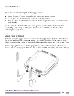
Attach the antennas to their correct connectors. For information on available antennas,
see
“Antenna Options” on page 11
.
6
Place the large center opening of each of the mount slots over the screw heads.
7
Slide the Access Point down along the mounting surface to hang the mount slots on the
screw heads
8
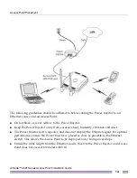
Cable the Access Point using an approved line cord and power supply.
For Power Injector installations:
a
Connect a RJ-45 CAT5e (or CAT6) Ethernet cable between the network data supply
(host) and the Power Injector
Data In
connector.
b
Connect a RJ-45 CAT5e (or CAT6) Ethernet cable between the Power Injector
Data &
Power Out
connector and the Access Point GE1/PoE port.
c
Ensure the cable length from the Ethernet source (host) to the Power Injector and
Access Point does not exceed 100 meters (333 ft). The Power Injector has no On/Off
power switch. The Power Injector receives power as soon as AC power is applied.
For more information on using the Power Injector, see
“Power Injector System” on
page 12
.
For power adapter (Part Number PWRS-147376-01R) and line cord installations:
a
Connect a RJ-45 CAT5e (or CAT6) Ethernet cable between the network data supply
(host) and the Access Point’s GE1/PoE.
b
Verify the power adapter is correctly rated according the country of operation.
c
Connect the power supply line cord to the power adapter.
d
Attach the power adapter cable to the DC-48V power connector on the Access Point.
e
Attach the power supply line cord to a power supply.
CAUTION
Do not connect to the power source until the cabling of the Access Point is complete.
Ensure PoE is not connected to the Access Point’s console connector or risk rendering the console
connector permanently inoperable.


