


EXTEL - WAVE - 720313
en - 4
E - INSTALLATION
3 - INSTALLING THE POWERBOX
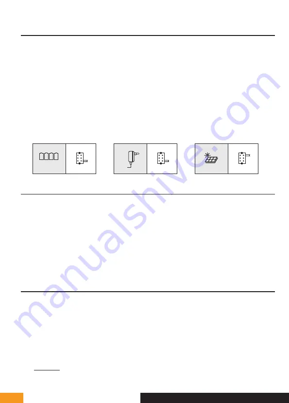
1. Insert 4 LR20 batteries in the electronic case or connect the power supply
(Fig.9)
to conduct the radio range
tests. Whenever possible, the antenna must be clear of any metal, source of interference or obstacles between
your case and your home; in particular, no contact between the antenna and tree leaves or branches. It must
also be placed high enough (approximately 1.60 m from the ground) and in a vertical position to obtain optimum
performance.
Note:
if the quality of transmission is insufficient, move the PowerBox to find a better position for the antenna
(higher and far from any obstacle).
2. Once the ideal location has been determined, carry out the final assembly.
3. Using 2 screws, secure the case via the 2 holes at the top and bottom, the antenna being at the top
(fig 4’)
4. Don’t forget to run the connection cable to the intercom panel first through the hole in the pillar and the
connecting wires to the gate motor drive or the electric strike plate.
Note:
Do not install any antenna other than the original one.
Managing Eco - Power mode
4 x LR20
Eco
Power
Eco
Power
Eco
Power
4 - CONNECTING AN ELECTRIC STRIKE PLATE
Directly connect the strike plate to the LOCK + and LOCK - terminals of the PowerBox (no polarity to be observed).
Important:
The electric strike plate opening function is only available when the PowerBox is powered by the power
supply unit provided (which itself is connected to the 230V power supply) and when Power mode is enabled.
Note that this function is only valid if the screen is on. The unit may buzz at the time the command is given.
For wiring, please refer to the diagram in
Fig9
.
Important:
• The maximum distance between the intercom panel and the electric strike plate or electric lock is 50 m
maximum. The wire size to be used is 0.75mm
²
.
• The use of a 12 V/1.1 A max. electric strike plate with WECA mechanical memory (
Extel reference 109021 or
109031
) or WECA 5001/2 10 SER R1 (
reference 150011
) is recommended.
5 - CONNECTING A MOTOR DRIVE
Directly connect it to the COM and NO terminals of the PowerBox (no polarity to be observed).
Note that this function is only valid if the screen is on. The panel provides a "dry" contact
connection, without an electric current, to connect to the button for your automated gate. For wiring, please refer
to the diagram in
Fig9
.
Important:
• The maximum distance between the intercom panel and the gate motor drive is 50 m maximum. The wire size
to be used is 0.75mm
²
.
• The product has been tested and approved with Thomson, Extel and Avidsen gate motors, which can be found
at
maisonic.fr
Содержание 720313
Страница 3: ...EXTEL WAVE 720313 Fig 4 Fig 4 1 5 6 7 3 4 Eco Power PAIR1 RESET LOCK COM NO 2...
Страница 4: ...EXTEL WAVE 720313 Fig 4 Eco Power PAIR1 LOCK COM NO Fig 5 50cm 160cm 150cm...
Страница 6: ...EXTEL WAVE 720313 Fig 8...
Страница 7: ...EXTEL WAVE 720313 Fig 9...
Страница 8: ...EXTEL WAVE 720313...
Страница 28: ...19 avenue Marcel Dassault ZAC des Deux Lions 37200 Tours France...


