background image

FIBER LINK #1

NAME = FBR:00

TYPE=62.5um MM

-22.05dBm 850nm

DATA

PRINT EDIT

NAME

SAVE

________________

|

|

|

|

wavelength as in step 2-7.   Repeat steps 2-7 through 2-10 for all 
wavelengths the user is setting a reference for.

2-12)

Press 

to continue.   The user will be returned to the 

MAIN MENU.

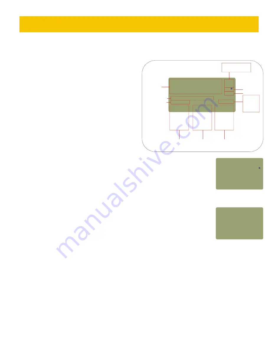
STEP 3 - TAKE READINGS

3-1)   Press   to TAKE READINGS.  The screen shown on the right 
will appear.   Take a moment to familiarize yourself with this screen.

 - toggles power units between dBm (ABS), dB (REL), and µm 

(ABS).   In dB (REL) mode, the power measurement changes to show 
the power level relative to the Link Wizard reference, and tells the 
user if the link passes or fails according to the EIA/TIA 568 cabling 
standard.   A power reading with a minus sign means that the link 
has failed the standard, and a plus sign means that the link passes.

 - stores the data point in memory for later download and report 

printing.  Each data point is conveniently stored with a user-

F1

3

F1

F2

definable name and an auto-numbering system.   In the diagram on the right, the label is the ‘FBR:’ in the 
Fiber ID field.  The ‘00 ‘ following the label is the auto-incrementing number.  Each time a data point is 
stored for a specific wavelength, this number goes up by 1.

 - toggles wavelength between 850nm, 1300nm, 1310nm, and 1550nm. 

3-2)   Press 

 to STORE a data point.  The user may be prompted to enter a label.   The user does not have 

to change this label, but it is recommended to set the label to better describe the fiber runs being stored.      
Press 

 to continue.

3-3)   The user will be prompted to enter the fiber type.   This fiber type must match the fiber type chosen in the 
Link Wizard.  Scroll through the fiber types with the 

 key, and press 

 to select.   The user will only have to 

enter the fiber type if they have not saved a data point for the current label.

3-4)   Press 

 to save the current data point and continue on to the next fiber.   

3-5)   Repeat steps 3-2 and 3-4 for each data point to save.  If the fiber label needs to be changed,               
press 

 at the Data Point Save Screen and repeat steps 3-2 through 3-4.

F3

F2

DONE

F1

F2

F3

F2

Fiber Certification, cont.

3-3

dBm (ABS)
dB (REL)
µW (ABS)

850nm
1300nm
1310nm
1550nm

Power Units

Temperature
Battery Life
Wavelength

F1

F2

F3

Toggle

Power

Units

Store

Data

Points

Toggle

Wave

Lengths

-20 45

.

_____________________

UNITS | STORE | WAVE

dBm

ABS

82

68%

850nm

Power

Measurement

FBR:00

FIBER LINK #1

Fiber Link Name

Fiber ID

dB (REL) Mode

PASS/FAIL

Data Point

Save Screen

3-6)   If the user is testing at additional wavelengths, press 

 to toggle to the next wavelength.   The auto-increment number will begin at 

‘00’ again, and have the same label.   Repeat steps 3-2 and 3-4 for each data point being saved.

STEP 4 - STORED DATA

Before downloading certification data points to a PC, the user must first have installed free Reporter software on it.  The software may be 
downloaded from http://owl-inc.com/literature/sub/htm/owl_reporter.htm.

4-1)   Press 

 to enter the MAIN MENU.

4-2)   Press   to enter STORED DATA.

4-3)   Press   to DOWNLOAD DATA.

F3

MENU

4

4

245

.

________________
UNITS|STORE|WAVE

dB

REL

82

68%

850nm

FBR:00

FIBER LINK #1

<PASS 568>

+

FIBER CERTIFICATION

UNIT 3

Содержание MO500

Страница 1: ...nual Firmware Version 1 20e September 15 2003 Part Numbers MO500 MO510 MO520 Extech 99 Washington Street Melrose MA 02176 Phone 781 665 1400 Toll Free 1 800 517 8431 Visit us at www TestEquipmentDepot com Back to the Extech MO500 Series Info Page ...

Страница 2: ...ta Menu 2 5 Power OFF 2 5 Unit 3 Fiber Certification Overview 3 1 Operation 3 1 Power ON 3 1 Fiber Certification 3 1 Definition of a Link 3 1 Required Equipment 3 1 Preparation 3 1 Reference Method 3 1 Step 1 Select Link 3 2 Step 2 Define Link 3 2 Step 3 Take Readings 3 3 Step 4 Stored Data 3 3 UNIT 4 Appendices Appendix A Decibel Review 4 1 Appendix B Dynamic Range Review 4 2 Appendix C Glossary ...

Страница 3: ...signed with these standards in mind because we understand the importance of qualifying your fiber installations with standards compliant test equipment The meter you have just purchased also prints professionally formatted reports showing the conformity to these popular industry standards You can print out these reports as a record of the original conformity to quality set by the standards These d...

Страница 4: ...for correct power levels and stability The transmitters in this equipment have a known power value The MicroMeter can be directly attached to this equipment via a patch cord to check whether the transmitter is stable and is within the manufacturer s specified power range Applications 1 1 Description The MicroMeter is a high accuracy high resolution microprocessor controlled optical power meter The...

Страница 5: ... to enter some input e g a fiber length measurement or a descriptive name for a fiber run This feature allows the MicroMeter to become more user friendly ALPHA NUMERIC FIELDS These fields allow the user to enter either a number a letter or a special character This is accomplished by pressing and holding the key until the desired character appears When the key is released the cursor automatically a...

Страница 6: ...erent units The user may toggle through these units by pressing dBm ABS This is an absolute ABS power measurement It shows how much optical power is being received by the photodetector in decibels referenced to a milliwatt dBm dB REL This is a relative REL power measurement It shows the amount of optical power being received by the photodetector relative to a user defined reference power i e zeroi...

Страница 7: ...the laser to warm up according to the manufacturer specifications to ensure accurate references NOTE When zeroing multiple wavelengths do NOT remove the patch cord from the light source Removing the patch cord from the light source will invalidate the optical reference for the wavelength that was just set Use a separate patch cord for each light source port Operation cont Wavelengths Zeroing the M...

Страница 8: ...on allows the user to view and download the data points previously stored in the meter This option allows the user to edit the owner information and adjust the LCD contrast Pressing from the MAIN MENU will return the user to the power reading display screen 3 TAKE READINGS 4 STORED DATA 5 METER SETUP DONE 2 3 1 SELECT LINK 2 DEFINE LINK 3 TAKE READINGS 4 STORED DATA MAIN MENU 5 METER SETUP Meter S...

Страница 9: ... link and press to change the name and or date Press to continue 3 Press to LOAD the selected link and press to continue 4 From the MAIN MENU press to DEFINE LINK Press to SET A MANUAL REFERENCE MENU 1 F3 DONE F2 DONE 2 2 NOTE setting a reference with this method will overwrite any previous certification or manual references F1 F2 DONE DONE 3 5 Press to scroll through the wavelengths and press to ...

Страница 10: ... device such as a serial printer or terminal program The printout is formatted in an easy to read format this option allows the user to delete a range of data points or delete all of the data points from the meter This should only be done after the data points have been downloaded into the PC with Reporter software this option allows the user to download data either to Reporter software or to a te...

Страница 11: ...make sure they are not adding significant loss to the test REFERENCE METHOD see Appendix I for more details For proper certification of fiber links using the MicroMeter use the following methods for setting certification references Single mode fiber EIA TIA 526 7 Method 1 A Multi mode fiber EIA TIA 526 14A Method B The Link Wizard calculates a PASS FAIL threshold according to the link attenuation ...

Страница 12: ...ct the light source for the wavelength shown on the display remember if the user is testing multi mode fibers the test jumper must be wrapped 5 7 times around a mandrel Press or to continue 2 8 The settings the user just entered will appear on the display see the example below SRC PWR shown in dBm actual power the light source is emitting 100 m shown in dB attenuation value associated with the len...

Страница 13: ... fiber runs being stored Press to continue 3 3 The user will be prompted to enter the fiber type This fiber type must match the fiber type chosen in the Link Wizard Scroll through the fiber types with the key and press to select The user will only have to enter the fiber type if they have not saved a data point for the current label 3 4 Press to save the current data point and continue on to the n...

Страница 14: ... Reporter we recommend that the user saves them as an Reporter file for permanent storage If hard copy of the data points is needed the data points may be printed There are two report options summary and detail The summary printout lists all of the data points together shows whether the link passed or failed and shows the power level of the fiber The detail printout prints each individual fiber ru...

Страница 15: ... scientists came up with a little trick to squeeze the graph down to a more presentable size The trick uses logarithms logs Logs are fairly simple most of us have already encountered logs in pre algebra class They didn t seem so important then but they are important to the understanding of decibels Logs expressed in Base 10 are just a way to state how many zeros there are in a number For example l...

Страница 16: ...ccuracy In the case of the MicroMeter the dynamic range is 75dB Any power level reaching the detector that is greater than 5 dBm is too powerful to accurately measure Likewise any power level below 70 dBm will be too weak to be sensed Power levels within the dynamic range produce acceptable readings It is interesting to note that the MicroMeter remains accurate over the upper 96 of the 75 dB dynam...

Страница 17: ...han that of the surrounding cladding Cross Connection A connection scheme between cabling runs subsystems and equipment using patch cords or jumpers that attach to connecting hardware on each end Decibel dB In fiber optics a standard logarithmic unit for the ratio of the power that was received over the power that was originally sent dBm Decibel referenced to a milliwatt dBµ Decibel referenced to ...

Страница 18: ...he loss of power that results from inserting a component such as a connector or splice into a previously continuous path Interconnection A connection scheme that provides for the direct connection of a cable to another cable or to an equipment cable without a patch cord or jumper Intermediate Cross Connect IC A cross connect between the main cross connect and the horizontal cross connect in backbo...

Страница 19: ... of the extent of a spectrum For a source the width of wavelengths contained in the output at one half of the wavelength of peak power Typical spectral widths are 20 to 60 nm for an LED and 2 to 5 nm for a laser diode Splice An interconnection method for joining the ends of two optical fibers in a permanent or semi permanent fashion Step Index Fiber An optical fiber either multi mode or single mod...

Страница 20: ...ure 30 to 70 C Size 3 48 W x 6 48 H x 1 1 D Weight 373g 12 oz Data Storage Points up to 1000 Download Data Points Reporter Software Absolute Relative Measurements Yes Battery Capacity Display Yes Backlight Yes NIST Traceable Yes Appendix D MicroMeter Specifications Appendix E Warranty Information 4 6 UNIT 3 APPENDICES APPENDICES UNIT 4 Test Equipment Depot 800 517 8431 99 Washington Street Melrose...

Страница 21: ...l begin to corrode the components 99 Isopropyl alcohol is very flammable so additional care must be taken when cleaning the detector 99 Isopropyl alcohol can be purchased at your local drug store 2 Whenever possible use specially designed 2 5mm cleaning sticks to clean the detector These do not require alcohol and do not damage the insides of the connector Do not used sticks or swabs of any other ...

Страница 22: ...nm LED Source w SC input LE220ST 850nm 1300nm LED Source w ST input LS300FC 1310nm Laser Source w FC input LS300SC 1310nm Laser Source w SC input LS300ST 1310nm Laser Source w ST input LS310FC 1550nm Laser Source w FC input LS310SC 1550nm Laser Source w SC input LS310ST 1550nm Laser Source w ST input LS320FC 1310 1550nm Laser Source w FC input LS320SC 1310 1550nm Laser Source w SC input LS320ST 13...

Страница 23: ...rate using the specified electronics Operating Wavelength Appendix H Link Budget Calculation Worksheet Total Cable Distance km Individual Fiber Loss at operating wavelength dB km Total Fiber Loss dB Individual Connector Loss dB Number of Connector Pairs Total Connector Loss dB Individual Splice Loss dB Number of Splices Total Splice Loss dB Other Components dB Total System Attenuation Fiber Loss C...

Страница 24: ...DE ONLY If you are testing multi mode fibers you will need to wrap each of the jumpers connected to the light source around a mandrel at least 5 times This is done to achieve Equilibrium Mode Distribution EMD which eliminates unwanted optical energy that can cause inaccurate test results Step 4 Run the Link Wizard You will be prompted to connect the patch cords during this process once for each wa...

Отзывы: