background image

Extech


Instruments


                                                                           26                                    GX900-EU-EN V1.6   4/14 


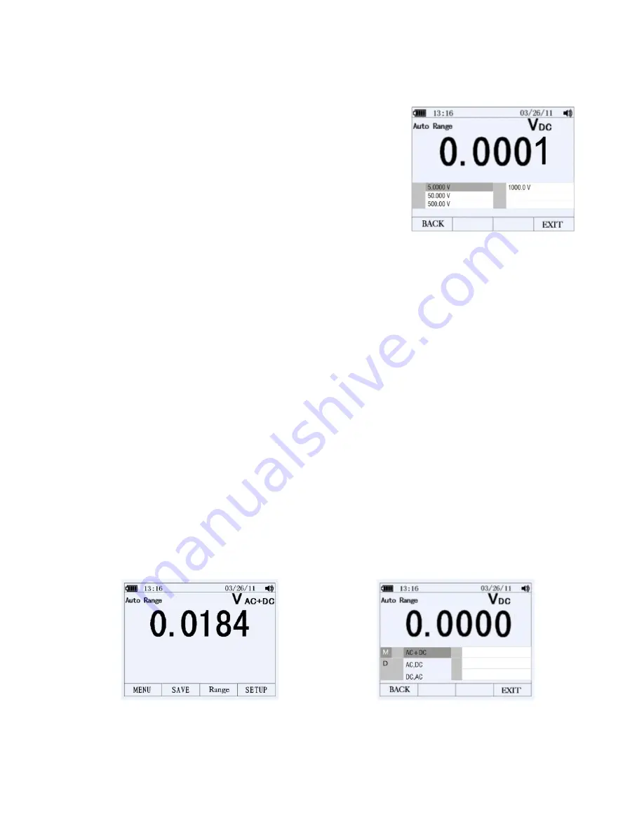
AUTOMATIC


AND


MANUAL


RANGING


Press


the


F3


key


(RANGE)


to


open


the


Range


menu.


Press


F1


key


(AUTO)


to


enable


the


Auto


Range


mode.


Press


F2


key


(MANUAL)


to


enable


the


Manual


Range


mode.


In


the


Manual


Range


mode,


move


the


menu


selector


to


the


desired


range.


AC


AND


DC


SIGNALS


This


meter


is


capable


of


displaying


both


AC


and


DC


signal


components


(voltage


or


current)


as


two


separate


readings


or


one


AC+DC


(RMS)


value


combined.


The


meter


displays


AC


and


DC


combinations


three


ways:


DC


displayed


over


AC


(DC,


AC)


AC


displayed


over


DC


(AC,


DC)


AC


combined


with


DC


(AC+DC)


Select


one


of


the


above


combinations


using


the


FUNCTION


and


MODE


menu


as


described


in


the


steps


below:


1.


With


the


rotary


switch


set


to


V,


mV,


A,


mA,


or


uA


press


the


key


labeled


MENU


2.


Move


the


menu


selector


to


the


menu


item


labeled


MATH


3.


Press


OK


4.


The


three


labels


(AC+DC,


AC/DC,


and


DC/AC)


will


appear


5.


Move


the


menu


selector


to


the


desired


menu


label


6.


Press


OK


While


in


any


of


the


three


modes


described


above


Peak


Measurements,


Frequency,


Duty


Cycle,


MAX

MIN,


Relative


%,


and


Period


Measurements


are


not


available


for


use.


Содержание GX900

Страница 1: ...USER GUIDE TRUE RMS INDUSTRIAL MULTIMETER MODEL GX900 99 Washington Street Melrose MA 02176 Phone 781 665 1400 Toll Free 1 800 517 8431 Visit us at www TestEquipmentDepot com ...

Страница 2: ...nic RPM Duty Cycle dBm dBV Diode Continuity and Temperature Built in datalogger and trend features store measurement data with convenient recall functionality Maximum reading MAX and Minimum Reading MIN memory features Reading HOLD feature for freezing displayed information with Auto Hold Intuitive TFT color LCD display and convenient keypad push button control On screen HELP utility for user hint...

Страница 3: ...EGORIES 6 CAUTIONS 7 SAFETY INSTRUCTIONS INPUT PROTECTION LIMITS 8 FCC COMPLIANCE 9 DESCRIPTIONS 10 METER DESCRIPTION 10 INPUT TERMINAL DESCRIPTION 10 KEYPAD DESCRIPTION 11 LCD DISPLAY DESCRIPTION 12 QUICK START GUIDE 13 MEASUREMENTS 14 DC VOLTAGE MEASUREMENTS 14 AC VOLTAGE MEASUREMENTS 15 dBm dBV AC MEASUREMENTS 15 LOW PASS FILTER FOR ACV MEASUREMENTS 16 DC AC MILLIVOLT MEASUREMENTS 16 ...

Страница 4: ...QUENCY DUTY CYCLE PULSE WIDTH PERIOD MEASUREMENTS 23 RPM MEASUREMENTS 24 COUNTER MEASUREMENTS 24 FUNCTIONS AND FEATURES 25 FUNCTION MENU BASICS 25 THE HELP UTILITY 25 AUTOMATIC AND MANUAL RANGING 26 AC AND DC SIGNALS 26 MINIMUM MIN AND MAXIMUM MAX READINGS 27 CAPTURING PEAK VALUES 28 RELATIVE MODE 28 DATA HOLD AND AUTO HOLD MODE 29 STORING INDIVIDUAL SCREEN SHOTS 29 VIEWING MEMORY DATA 29 VIEW TRE...

Страница 5: ...ESHOLD VALUE 33 CHANGE CALIBRATION PASSWORD 33 CALIBRATION ACCESS 34 BLUETOOTHTM CAPABILITY 34 GX900 SOFTWARE 34 SETTING THE DATE AND TIME 35 AUTOMATIC POWER OFF 35 TIME AND DATE FORMATS 36 NUMERIC FORMAT 36 LANGAUGE FORMAT 36 BATTERY AND FUSE REPLACEMENT 37 BATTERY REPLACEMENT 37 FUSE REPLACEMENT 38 SPECIFICATIONS 39 GENERAL SPECIFICATIONS 39 ELECTRICAL SPECIFICATIONS 40 ...

Страница 6: ...t in damage to the instrument IEC1010 OVERVOLTAGE INSTALLATION CATEGORIES OVERVOLTAGE CATEGORY I Equipment of OVERVOLTAGE CATEGORY I is equipment for connection to circuits in which measures are taken to limit the transient over voltages to an appropriate low level Examples include protected electronic circuits OVERVOLTAGE CATEGORY II Equipment of OVERVOLTAGE CATEGORY II is energy consuming equipm...

Страница 7: ...before performing Diode Resistance or Continuity tests Voltage checks on electrical outlets can be difficult and misleading because of the uncertainty of connection to the recessed electrical contacts Other means should be used to ensure that the terminals are not live If the equipment is used in a manner not specified by the manufacturer the protection provided by the equipment may be impaired Th...

Страница 8: ...ms 2 USE EXTREME CAUTION when working with high voltages 3 DO NOT measure voltage if the voltage on the COM input jack exceeds 1000V above earth ground 4 NEVER connect the meter leads across a voltage source while the function switch is in the current resistance or diode mode Doing so can damage the meter 5 ALWAYS discharge filter capacitors in power supplies and disconnect the power when making r...

Страница 9: ...ent generates uses and can radiate radio frequency energy and if not installed and used in accordance with the instructions may cause harmful interference to radio communications However there is no guarantee that interference will not occur in a particular installation If this equipment does cause harmful interference to radio or television reception which can be determined by turning the equipme...

Страница 10: ...ht control 11 Information button 12 Navigation arrow keys and OK confirmation button Note Battery compartment and tilt stand are located on the rear of the instrument INPUT TERMINAL DESCRIPTION All functions excepting current use the V and COM input terminals Separate terminals are provided for current above 500mA and for current below 500mA Input for 0 A to 10 00 A current Input for 0 A to 500 mA...

Страница 11: ...MAX MIN button Starts and stops the Maximum MAX and Minimum MIN reading memory OK button Confirms data entry Rotary Switch Selects the primary measurement function for each the meter presents a standard display for that function range measurement units and modifiers See table below V AC voltage measurements V DC and AC DC voltage measurements mV DC AC millivolts ac dc millivolt Temperature Clamp C...

Страница 12: ... icon when necessary in this area 9 Main display provides measurement information regarding the input signal 10 Date indicates the date set for the internal clock 11 Beeper indicates the Meter s audible feedback is enabled this is not associated with the continuity beeper 12 Unit indicates the units of measure Auxiliary Units indicates measurements that use factors instead of units such as Crest F...

Страница 13: ...st as described in this Instruction Manual s section related to the test in question Step Five Safely perform the test as described in this Instruction Manual Step Six Read the measurement value on the LCD display Step Seven Carefully disconnected the meter s test leads from the circuit or device under test Step Eight Read the section of this Instruction Manual entitled Features and Functions to l...

Страница 14: ...e to a higher range or use the Auto range mode DC VOLTAGE MEASUREMENTS CAUTION Do not measure DC voltages if a motor on the circuit is being switched ON or OFF Large voltage surges may occur that can damage the meter 1 Set the function switch to the V position 2 Insert the black test lead banana plug into the negative COM jack Insert the red test lead banana plug into the positive V jack 3 Touch t...

Страница 15: ...t lead banana plug into the positive V jack 3 Touch the black test probe tip to the neutral side of the circuit Touch the red test probe tip to the hot side of the circuit 4 Read the voltage in the display dBm dBV AC MEASUREMENTS The meter is capable of displaying AC voltage as a dB value relative to 1 milli watt dBm relative to 1V dBV or to a custom reference value 1 Set the function switch to th...

Страница 16: ... DC AC MILLIVOLT MEASUREMENTS CAUTION Do not measure DC AC voltages if a motor on the circuit is being switched ON or OFF Large voltage surges may occur that can damage the meter 1 Set the function switch to the mV position 2 Press the F1 key MENU move the menu selector to the menu item labeled mVDC or mVAC and then press the OK key 3 Select mVDC or mVAC from the key options and press the OK key 4...

Страница 17: ...ENU move the menu selector to the item labeled CLAMP DC AC and then press the OK key 4 Select the item labeled RANGE 0 1 100mV A and then press the OK key 5 Connect the remote clamp to the input terminal jacks ensuring proper polarity Insert the clamp s negative lead into the negative COM jack and connect the clamp s positive lead into the meters positive V jack 6 Read the measurement in the displ...

Страница 18: ...measurements up to 500mA DC set the function switch to the mA position and insert the red test lead banana plug into the µA mA jack Press the F1 key MENU and select mADC Press the OK key 4 For current measurements up to 10A DC set the function switch to the 10A position and insert the red test lead banana plug into the 10A jack Press the F1 key MENU and select ADC Press the OK key 5 Remove power f...

Страница 19: ...switch to the mA position and insert the red test lead banana plug into the µA mA jack Press the F1 key MENU and select mAAC Press the OK key 4 For current measurements up to 10A AC set the function switch to the 10A position and insert the red test lead banana plug into the 10A jack Press the F1 key MENU and select AAC Press the OK key 5 Press the key labeled MENU move the menu selector to the it...

Страница 20: ... unplug the line cords 1 Set the function switch to the Ω CAP position 2 Insert the black test lead banana plug into the negative COM jack 3 Insert the red test lead banana plug into the positive Ω jack 4 Touch the test probe tips across the circuit or part under test It is best to disconnect one side of the part under test so the rest of the circuit will not interfere with the resistance reading ...

Страница 21: ... circuit or wire under test 7 If the resistance is less than approximately 35 Ω the audible signal will sound If the circuit is open the display will indicate OL DIODE TEST 1 Set the function switch to the Ω CAP position 2 Press the F1 key MENU move the menu selector to the DIODE field and then press the OK key 3 Move the menu selector to the item labeled DIODE and press the OK key 4 Insert the bl...

Страница 22: ... 30 seconds 6 Read the temperature in the display To input a temperature offset value press the F3 key OFFSET A message box will appear showing the currently selected offset value Use the right left arrow keys to position the cursor over one of the digits or the polarity sign Then use the up down arrows to edit the selected digit or polarity sign With the desired value displayed press the F1 key O...

Страница 23: ...ead banana plug into the negative COM jack 5 Insert the red test lead banana plug into the positive V jack 6 Touch the test leads to the capacitor to be tested 7 Read the capacitance value in the display FREQUENCY DUTY CYCLE PULSE WIDTH and PERIOD MEASUREMENTS ELECTRONIC 1 Set the rotary function switch to the Hz position 2 Press the F1 key MENU move the menu selector to the menu item of your choi...

Страница 24: ...to the item labeled COUNTER and then press the OK key 3 Move the menu selector to the item labeled START and press the OK key 4 Insert the black test lead into the negative COM jack and the red test lead into the positive V jack 5 Touch the test probe tips to the circuit under test 6 Read the Period value on the display 7 To set the Count Threshold press the F1 key MENU move the menu selector to t...

Страница 25: ...between menu items the four F keys and OK key change to reflect the available functions and or modes available for the selection menu item THE HELP UTILITY While operating the meter additional information regarding a selected function a front panel button or a menu may be needed Press the INFO key to open an information window that lists topics covering the functions and modifiers that are availab...

Страница 26: ...ned The meter displays AC and DC combinations three ways DC displayed over AC DC AC AC displayed over DC AC DC AC combined with DC AC DC Select one of the above combinations using the FUNCTION and MODE menu as described in the steps below 1 With the rotary switch set to V mV A mA or uA press the key labeled MENU 2 Move the menu selector to the menu item labeled MATH 3 Press OK 4 The three labels A...

Страница 27: ...r maximum valued To activate the MIN MAX mode press the MIN MAX button the display will indicate the MIN MAX values at the top of the measurement page The start date and time are indicated at the bottom of the measurement page In addition the recorded MIN MAX AVG values appear in the secondary display with their respective elapsed timers To stop a MIN MAX recording session press the key labeled ST...

Страница 28: ...e CREST F label and then press OK to start the PEAK recording session RELATIVE MODE To activate the Relative mode press the F1 key MENU and move the menu selector next to the menu item labeled REL REL and then press the OK key Move the menu selector to the REL or the REL label and press OK to start the Relative mode If the meter is currently in the Relative mode pressing REL causes the meter to sw...

Страница 29: ...uto Hold threshold for at least one second The meter filters open lead conditions so that the meter leads can be moved between test points without triggering a display update STORING INDIVIDUAL SCREEN SHOTS For all measurement functions a snapshot of the screen data is saved by pressing the key labeled SAVE VIEWING MEMORY DATA Viewing data stored in the meter s memory is performed through the SAVE...

Страница 30: ...ect menu item LOG and Press the OK key If there are previously stored records press the F1 key PREV to page through them or press the F2 key NEXT to scroll in the opposite direction Press F4 CLOSE to return the meter to the normal operating mode Press the F3 key TREND to display the recorded data in a trend plot view Press the F2 key DELETE to clear recorded data Press the F3 key SUMMARY to get ba...

Страница 31: ... the other to fit the recording session in the available memory Adjust these by using the up and down menu arrows to select either Duration or Sample rate Press OK key to select Press F1 key EDIT to edit the parameter press the OK key to enable editing Use the left and right menu arrow keys to select the unit to change press F1 key OK to save your changes The percentage of memory available at the ...

Страница 32: ...eral operations and are active in all functions while others are limited to one function or one group of functions Meter information such as serial number model etc is also available in the Setup mode Access to the setup options is available by pressing the F4 key SETUP RESET THE METER SETUP OPTIONS The meter s setup options can be reset to factory default conditions through the Setup menu 1 Open ...

Страница 33: ...3 Position the menu selector next to the menu item labeled THRESHOLD and press OK 4 Position the menu selector next to the menu item labeled EDIT and press OK 5 Use the up and down arrow keys to change the event threshold values 6 With the desired value selected press theF1 key OK to confirm the change or press the F4 key Cancel to cancel the change CHANGE CALIBRATION PASSWORD The Calibration sele...

Страница 34: ...calibration instructions BLUETOOTHTM CAPABILITY A Bluetooth communication link can be used to connect to the GX900 software It will also allow you to monitor the meter from an Android device using ExView 1 Open the setup menu by pressing the F4 key SETUP 2 Position the menu selector next to the INSTRUMENT label and press OK 3 Position the menu selector next to the COMMUNICATE label and press OK 4 ...

Страница 35: ...position the cursor on the date or time element to adjust it 5 Use the up and down arrows to change the selected date or time values 6 Press the F1 key OK to complete and confirm the actions AUTOMATIC POWER OFF 1 Open the Setup menu by pressing the F4 Key SETUP 2 Position the menu selector next to INSTRUMENT and press OK 3 Position the menu selector next to SETTINGS and press OK 4 Position the men...

Страница 36: ...s F3 CANCEL to exit without changing the format NUMERIC FORMAT 1 Press the F4 key SETUP 2 Position the menu selector next to the item labeled DISPLAY and press OK 3 Position the menu selector next to the item labeled FORMAT and press OK 4 Position the menu selector next to the item labeled NUMERIC and press OK 5 Select F1 0 000 or F2 0 000 or F4 CANCEL LANGAUGE FORMAT 1 Press the F4 key SETUP 2 Po...

Страница 37: ...ies responsibly Observe local state and federal regulations with regard to battery disposal Never dispose of batteries in a fire Batteries may explode or leak Never mix battery types Always install new batteries of the same type Never dispose of used batteries or rechargeable batteries in household waste As consumers users are legally required to take used batteries to appropriate collection sites...

Страница 38: ...emove the battery compartment cover 3 Remove the fuse from the battery compartment by first carefully prying one end loose and then sliding the fuse from its bracket 4 Install only specified replacement fuses 5 Replace the battery compartment cover 800mA 1000V ceramic 6 3mm x 32mm SIBA 7017240 0 8 10A 1000V ceramic 10mm x 38mm SIBA 5019906 10 ...

Страница 39: ...tery icon displayed when battery drops below operating voltage Fuses FF 0 8A 1000V 6 3x32mm SIBA 7017240 0 8 FF 10A 1000V 10x38mm SIBA 5019906 10 Operating Temperature 5 C to 40 C 41 F to 104 F Operating Humidity Max 80 up to 31 C 87 F decreasing linearly to 50 at 40 C 104 F Storage Temp Humidity 20 C to 60 C 4 F to 140 F 80 Operating Altitude 2000m 7000 ft max Safety This meter protected by doubl...

Страница 40: ...0V 0 001V 500V 0 01V 1000V 0 1V Accuracy for all AC voltage ranges are specified from 5 of range to 100 of range Function Range Resolution Accuracy AC DC 0 to 1000Hz 50mV 0 001mV 1KHZ 1 25 10KHZ 3 5 25 500mV 0 01mV 5V 0 0001V 50V 0 001V 500V 0 01V 1000V 0 1V 1 Add 1 above 5k Function Range Resolution Accuracy DC Current 500µA 0 01µA 0 1 20 5000µA 0 1µA 50mA 0 001mA 500mA 0 01mA 0 15 20 10A 0 001A ...

Страница 41: ...o 28 C 65 to 83 F and 75 RH for calibration using a pure sine wave Function Range Resolution Accuracy Resistance 50Ω 1 0 001Ω 0 5 20 500Ω 1 0 01Ω 0 05 10 5kΩ 0 0001kΩ 0 05 10 50kΩ 0 001kΩ 500kΩ 0 01kΩ 0 2 10 5MΩ 0 0001MΩ 0 2 20 50MΩ 0 001MΩ 2 20 1 Use the relative mode REL Q to compensate for offsets Function Range Resolution Accuracy Capacitance 5nF 0 001nF 2 40 50nF 0 01nF 500nF 0 1nF 2 40 digit...

Страница 42: ...reading Sensitivity 2V RMS Function Range Resolution Accuracy Duty Cycle 0 1 to 99 90 0 01 1 2 reading 2 digits Pulse width 100µs 100ms Frequency 5Hz to 150kHz Function Range Resolution Accuracy RPM 0 01 10 Count 0 5 10 Clamp DC 0 1 100mV A 0 1A 0 0001A Clamp 0 5 Clamp AC 0 1 100mV A 0 1A 0 0001A Clamp 0 5 Function Range Resolution Accuracy Temperature type K 50 to 1000 C 0 1 C 1 0 reading 2 5 C 5...

Отзывы: