6
AC Current Measurements
WARNING:
Ensure that the test leads are
disconnected from the meter before making current
clamp measurements.
1.
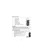
Set the Function switch to the
600 or 200A
range.
If the range of the measured is not known, select
the higher range first then move to the lower
range if necessary.
2.
Press the trigger to open jaw. Fully enclose one
conductor to be measured.
3.
The clamp meter LCD will display the reading.
Resistance and Continuity Measurements
1.
Insert the black test lead into the negative
COM
terminal and the
red test lead into the
Ω
terminal.
2.
Set the function switch to the
Ω
•)))
position.
3.
Touch the test probe tips across the circuit or component under
test. It is best to disconnect one side of the device under test so the
rest of the circuit will not interfere with the resistance reading.
4.
For Resistance tests, read the resistance on the LCD display.
5.
For Continuity tests, if the resistance is < 40
Ω
, a tone will sound.
Data Hold
To freeze the LCD meter reading, press the data hold button. The data
hold button is located on the left side of the meter (top button). While
data hold is active, the
DH
display icon appears on the LCD. Press the
data hold button again to return to normal operation.
Peak Hold
To hold the highest reading on the LCD, press the peak hold button. The
peak hold button is located on the left side of the meter (bottom button).
The meter reading will not change as readings change, rather it will only
display the highest reading encountered since the peak hold button was
pressed. Press the peak hold button again to return to normal operation.


