background image

16


English


EX

-

45362


5. Hardware Installation 


If you are ready with the jumper settings, please proceed with the following installation 
instructions. Because there are large differences between PC

s, we can give you only a 

general  installation  guide  for  the  EX

-

45362.  Please  refer  to  your  computer

s  reference 

manual whenever in doubt.


1.


Turn off the power to your computer and any other connected peripherals.


2.


Remove the mounting screws located at the rear and/or sides panels of your Com-
puter and gently slide the cover off.


3.


Locate  an  available  expansion  slot  and  remove  its  covers  from  the  rear  panel  of 
your  computer.  Make  sure  it  is  the  right  expansion slot  for  the  card  (see  card  de-
scription)


4.


Align the card with the PCI

-

Express slot and then gently but firmly, insert the card. 

Make sure the card is seated and oriented correctly. Never insert the card by force!


5.


Then connect the card with a screw to the rear panel of the computer case.


6.


Gently replace your computer

s cover and the mounting screws.


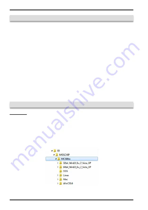
6. Driver Installation 


Windows


After  completing  the  hardware  installation,  the  operating  system  will  automatically  the 
card and install this! If the driver should not be installed automatically, insert the driver 
CD  into  you  CD

-

ROM  drive  (eg  drive  D:)  and  then  open  the  folder 

IO/MOSCHIP/

MCS99xx

“. 

Please  select  the  folder  with  your  operating  system  and  install  the  driver 

(see Picture). Follow the hardware assistant and finish the installation. 

Important! 

Re-

start your PC in any case after installing the drivers.


Содержание EX-45362

Страница 1: ...RS 232 422 485 PCI Express Karte mit 2 x 9 Pin Anschluss EX 45362 Anleitung Vers 1 0 03 12 20 Manual RS 232 422 485 PCI Express Card with 2 x 9 Pin Connector...

Страница 2: ...nstellungen 7 5 Hardware Installation 8 6 Treiber Installation 8 9 7 Technische Daten 10 1 Description 11 2 Extent of Delivery 11 3 Layout and Connections 12 3 1 Layout 12 3 2 Connections 12 4 Switch...

Страница 3: ...ren des Betriebssys tems automatisch vorgenommen werden ber die Jumper k nnen Sie 5V oder 12V auf Pin 9 des seriellen Anschluss umleiten Achten Sie bitte darauf dass die Angeschlosse nen Ger te dies a...

Страница 4: ...S DB9 EX 45362 DB9 Endger t 1 TXD 1 TCD 2 TXD 2 TXD 3 RXD 3 RXD 4 RXD 4 RXD 5 GND 5 GND 1 2 3 Aufbau und Anschl sse S1 S2 25 Pin Buchse f r Octopus Kabel mit 2 x 9 Pin Serielle Anschl sse S1_PWR 2_PWR...

Страница 5: ...Terminierung der Signale RX RX TX und TX zust ndig siehe Bild auf Seite 4 unter Aufbau Die Einstellungen sind f r jeden seriellen Port individuell einstellbar Der obere DIP Switch ist f r den Port 1 S...

Страница 6: ...4 Switch und Jumper Einstellungen 4 1 Switch Einstellungen Mode Terminator Switch S1_MODE S2_MODE Resistoren f r RS 422 RS 485 2 Draht und RS 485 4 Draht Mode Resistoren Off Resistoren On Terminator...

Страница 7: ...oard Werkseinstellung I12 12Volt vom Mainboard Werkseinstellung RI Am Pin 9 liegt das Standard Signal RI Ring Indicator an Werkseinstellung 5 Am Pin 9 liegt jetzt eine Spannung von 5V DC an 12 Am Pin...

Страница 8: ...Sie sicher das es sich um den richtigen Steckplatz handelt 4 Beachten Sie das die Karte korrekt eingesteckt wird und das kein Kurzschluss ent steht Wenden Sie bitte keine Gewalt an um die Karte einzus...

Страница 9: ...lliert Windows Server 2003 XP Treiber Windows Server 2008 VISTA Treiber Windows Server 2008R2 Windows 7 Treiber Windows Server 2012 Windows 8 x Treiber Windows Server 2012R2 Windows 10 Treiber BERPR F...

Страница 10: ...Buchse zum Anschluss vom Octopus Kabel Hardwaresystem PCI Express x1 bis x16 Betriebssystem Windows 2000 XP Vista 7 8 x 10 Server 20xx Mac Linux Betriebstemperatur 0 bis 55 Celsius Lagertemperatur 20...

Страница 11: ...will be obtained auto matically by the system BIOS and operating system With the jumpers you can enable 5V or 12V power to pin 9 Please note if you use power to pin 9 your peripheral device must supp...

Страница 12: ...8 CTS DB9 EX 45362 DB9 Device 1 TXD 1 TCD 2 TXD 2 TXD 3 RXD 3 RXD 4 RXD 4 RXD 5 GND 5 GND 1 2 3 Layout and Connections S1 S2 25 Pin connector for octopus cable with 2 x 9 Pin serial connector S1_PWR 2...

Страница 13: ...or RS 485 4 wire and for the signal termination for RX RX TX and TX see picture on page 12 under layout The settings can be set individually for each serial port The DIP switch at the top are respons...

Страница 14: ...EX 45362 4 Switch and Jumper Settings 4 1 Switch Settings Mode Terminator Switch S1_MODE S2_MODE Resistors for RS 422 RS 485 2 wire and RS 485 4 wire mode Resistor Off Resistor On Terminator Off Term...

Страница 15: ...5Volt from Mainboard Factory Setting I12 12Volt from Mainboard Factory Setting RI The pin 9 is connected with RI Ring Indicator signal Factory Setting 5 At pin 9 is now a voltage of 5V DC 12 At pin 9...

Страница 16: ...n slot for the card see card de scription 4 Align the card with the PCI Express slot and then gently but firmly insert the card Make sure the card is seated and oriented correctly Never insert the car...

Страница 17: ...indows Server 2003 XP Driver Windows Server 2008 VISTA Driver Windows Server 2008R2 Windows 7 Driver Windows Server 2012 Windows 8 x Driver Windows Server 2012R2 Windows 10 Driver CHECK INSTALLED DRIV...

Страница 18: ...n Connector for connect the Octopus Cable Hardware System PCI Express x1 to x16 Operating System Windows 2000 XP Vista 7 8 x 10 Server 20xx Mac Linux Operating Temperature 32 F to 131 Fahrenheit Stora...

Отзывы: