

6
5
1
JP2:
Power auf 9 Pin
Stecker Ein/Aus
JP3:
Jumper für die Stromquelle
(Netzteil oder PCI
-
Express Bus)
J5:
Anschluss für Strom
vom PC Netzteil
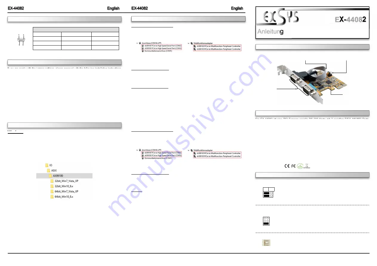
Die EX
-
44082 ist eine PCI
-
Express serielle RS
-
232 Karte mit 2 seriellen FIFO 16C550 Ports,
für den Anschluss von High
-
Speed seriellen RS
-
232 Peripherie Geräten (z.B. Terminal, Mo-
dem, Plotter usw.). Der serielle PCI
-
Express Bus unterstützt dabei optimal die Leistung des
schnellen ASIX Chipset. Die Karte gewährleistet so eine sichere Datenübertragung und exzel-
lente Performance von bis zu 115,2KBaud/s! Sie unterstützt alle PCI
-
Express Slots von x1 bis
x16. Es ist nicht möglich die I/O Adressen und Interrupts manuell einzustellen, da die Einstel-
lungen der Karte vom System (BIOS) und vom Betriebssystem automatisch vorgenommen
werden. Im Lieferumfang sind zusätzlich zwei LowProfile Bügel enthalten, für den Einbau in
schmale Gehäuse.
BESCHREIBUNG & TECHNISCHE DATEN
JUMPER
EINSTELLUNG & ANSCHLÜSSE
Anleitung
Vers. 1.0 / 25.05.20
EX
-
44082
AUFBAU
If you are ready with the jumper settings, please proceed with the following installation instructions.
Because there are large differences between PC’s, we can give you only a general installation
guide. Please refer to your computer’s reference manual whenever in doubt.
1.
Turn off the power to your computer and any other connected peripherals.
2.
Remove the mounting screws located at the rear and/ or sides panels of your Computer and
gently slide the cover off.
3.
Locate an available expansion slot and remove its covers from the rear panel of your comput-
er. Make sure it is the right expansion slot for the card (see card description)
4.
Align the card with the expansion slot, and then gently but firmly, insert the card. Make sure
the card is seated and oriented correctly. Never insert the card by force!
5.
Then connect the card with a screw to the rear panel of the computer case.
6.
Gently replace your computer’s cover and the mounting screws.
HARDWARE INSTALLATION
JUMPER
SETTING & CONNECTORS
DB 9M:
Pin
Signal
Pin
Signal
Pin
Signal
1
CDC
4
DTR
7
RTS
2
RXD
5
GROUND
8
CTS
3
TXD
6
DSR
9
RI
Serial 9 Pin D
-
SUB Connector
Windows
After completing the hardware installation, the operating system will automatically the card and
install this! If the driver should not be installed automatically, insert the driver CD into you CD
-
ROM drive (eg drive D:) and then open the folder „
IO/ASIX/AX99100
“. Please select the folder
with your operating system and install the driver (see Picture). Follow the hardware assistant
and finish the installation.
Important!
Restart your PC in any case after installing the drivers.
DRIVER INSTALLATION
DRIVER INSTALLATION
CHECK INSTALLED DRIVER
Open the >
Device manager
<. Now you should see at „
Ports (COM & LPT)
“ and at
„
Multifunction Adapter
“ the following new entry's:
If you see this or a similar information the device is installed correctly.
CHANGE PORT NUMBER
If you like to change the port number for example COM3 to COM5, open the „
Device Manager
”
click at „
COM3
”,
„
Settings
”
and then „
Advance
”. There you can change between COM3 till
COM256.
Windows Server 20xx
After completing the hardware installation, the operating system will automatically the card and
install this! If the driver should not be installed automatically, insert the driver CD into you CD
-
ROM drive (eg drive D:) and then open the folder „
IO/ASIX/AX99100
“. Please select the folder
with your operating system and install the driver (see Picture). Follow the hardware assistant
and finish the installation.
Important!
Restart your PC in any case after installing the drivers.
Use the following driver for the following Windows Server Version.
Windows Server 2003
=
XP Driver
Windows Server 2008
=
VISTA Driver
Windows Server 2008R2
=
Windows 7 Driver
Windows Server 2012
=
Windows 8.x Driver
Windows Server 2012R2
=
Windows 10 Driver
CHECK INSTALLED DRIVER
Open the >
Device manager
<. Now you should see at „
Ports (COM & LPT)
“ and at
„
Multifunction Adapter
“ the following new entry's:
If you see this or a similar information the device is installed correctly.
CHANGE PORT NUMBER
If you like to change the port number for example COM3 to COM5, open the „
Device Manager
”
click at „
COM3
”,
„
Settings
”
and then „
Advance
”. There you can change between COM3 till
COM256.
LINUX
The required Linux driver are located in the following directory
„
IO/ASIX/AX99100/Linux
“.
S1 & S2:
9 Pin Stecker
Seriell Anschluss
Kompatibilität:
PCI
-
Express x1 bis x16
Betriebssysteme:
Windows 2000/ XP/ Vista/ 7/ 8.x/ 10/ Server 20xx/ Linux
Anschlüsse:
2x 9 Pin Seriell Anschluss, 1x 4 Pin Floppy Anschluss
Lieferumfang:
EX
-
44082, Treiber CD, Anleitung, 2x LowProfile Bügel
Zertifikate:
DIS
PWR
S1
S2
JP2:
DIS
=
Am Pin 9 liegt das Standard Signal RI (Ring Indicator)
(Werkseinstellung)
PWR
=
Am Pin 9 kann jetzt eine Spannung von DC5V oder DC12V
eingestellt werden
Die Einstellung der Spannung nehmen Sie mit dem JP3 vor. Dies sollte
aber bei Standard Anwendungen nicht verstellt werden.
JP3:
Wenn Sie den Jumper JP2 für auf PWR gesetzt haben, können Sie mit
dem Jumper JP3 den Spannungswert einstellen. Es gibt 3 verschiedene
Spannungsquellen.
AUX5V
=
5Volt vom PC
-
Netzteil
(Werkseinstellung)
AUX12V
=
12Volt vom PC
-
Netzteil
PCI12V
=
12Volt vom Mainboard
PCI12V
AUX12V
AUX5V
J5:
1 +5V
2 GND
3 GND
4 +12V
Für AUX Einstellung (JP3) muss J5 mit PC Netzteil verbunden
werden! Sonst wird die Karte nicht mit Strom versorgt.


