

6
5
EX
EX
EX
-
-
-
41150
41150
41150
English
English
English
EX
EX
EX
-
-
-
41150
41150
41150
English
English
English
Windows Server 200x:
After starting Windows it recognizes a new “PCI Controller“ and open the hardware
assistant. Please choose manual installation and put the driver CD into your CD-Rom
drive. Now enter the Path "D:\IO\NETMOS\98XX" and then the directory of your oper-
ating system for Server 2000: “WIN2000“ for Server 2003: “WINXP“ or “WINXP_64“
and for Server 2008: “Vista32“ or “Vista64“ into the box for the Path/Source and click
at >next/continue<. Now Windows search for the drivers in the specified directory.
Follow the hardware assistant and finish the installation. If Windows recognizes other
new devices repeat the above described steps. Attention! Restart Windows in any
case after installing the drivers.
CHECK THE INSTALLED DRIVER:
Click at Start<>Run< then enter “compmgmt.msc“ and click at >OK<. In the windows
that open select >Device Manager<. Under „Ports (COM and LPT)“ you should find
one or more new ”PCI Ports“ as sample (COM3). If you see this or similar entries the
card is installed correctly.
CHANGE PORT NUMBER:
If you like to change the port number for example COM 3 to COM5, open the >Device
Manager< click at >COM3<, >Settings< and then >Advance<. There you can change
between COM 3 to 256. The LPT ports can be changed in the same way!
LINUX:
There are no drivers available for Linux, but the card is supported by the most versions
of Linux. Because each individual distribution and kernel version of Linux is different,
sadly we cant provide a installation instruction. Please refer to the installation manual
for standard IO ports from your Linux version! In some newer versions the card will
even be installed automatically after starting Linux.
MS-DOS:
Copy the DOS driver file from the CD (D:\IO\NETMOS\98XX\DOS\NmDosln.exe) to the
root directory on your hard disk (C:\). Modify the “AUTOEXEC.BAT“ with the following line:
C:\NmDosln -a -r
After you reboot DOS , you can see the card with COM3 and COM4. The IRQ its set from
System-BIOS and can’t be changed.
1
JUMPER EINSTELLUNG & ANSCHLÜSSE:
Die EX-41150 ist eine PCI serielle RS-232 Karte mit zwei seriellen FIFO 16C95x Ports,
für den Anschluss von High-Speed seriellen RS-232 Peripherie Geräten (z.B. Terminal,
Modem, Plotter usw.) und einem Parallelen Bi-Direktionalen EPP/ECP Ausgang für den
Anschluss von Peripheriegeräten mit Standard Centronics Interface (z.B. Drucker, Scan-
ner, Laufwerke usw.). Sie unterstützt den 32 und 64-Bit PCI bzw. PCI-X Bus mit 5 Volt
und 3,3 Volt. Es ist nicht möglich die I/O Adressen und Interrupts manuell einzustellen,
da die Einstellungen der Karte vom System (BIOS) und beim Installieren des Betriebs-
systems automatisch vorgenommen werden. Es besteht bei Bedarf die Möglichkeit, +5V
- oder +12V auf einen von vier Pins der beiden Stecker zu legen (POS System).
BESCHREIBUNG & TECHNISCHE DATEN :
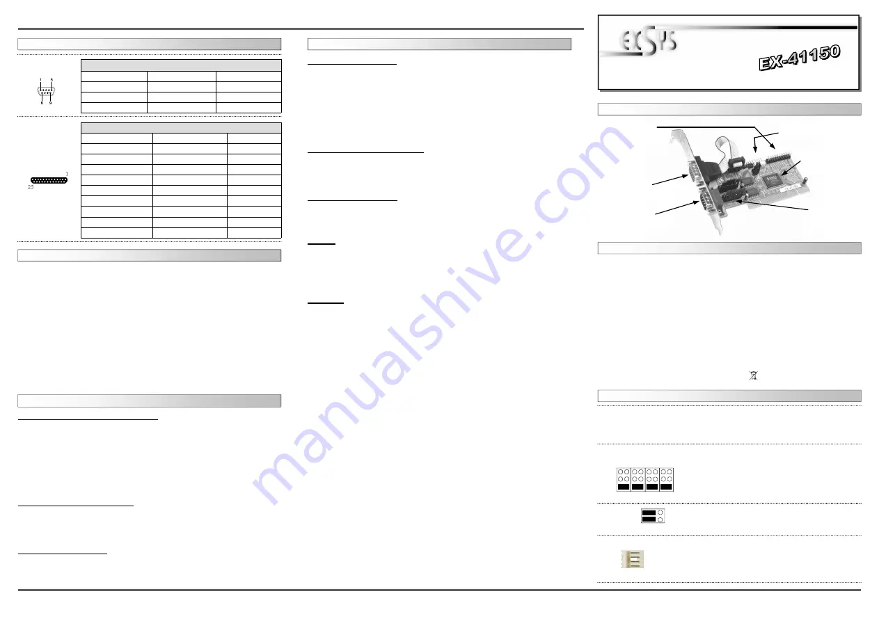
AUFBAU :
Kompatibilität:
PCI & PCI-X 3,3Volt & 5Volt bei 33Mhz
Betriebs Systeme:
DOS/ ME/ 2000/ XP/ Vista/ 7/ 8/ Server200x/ (Linux v. OS)
Anschlüsse:
2 x 9 Pin Seriell D-SUB Stecker, 1 x 25 Pin parallel Buchse
Lieferumfang:
EX-41150, Treiber CD, Deutsche Anleitung, 1x 25 Pin Kabel
Zertifikate:
CE
CE
CE
CE
/ FCC / RoHS / WEEE DE97424562 / WHQL
DRIVER INSTALLATION :
Sie haben die Mögli5V- oder +12V auf einen der folgenden vier Pins, der Stecker S1
und S2 zu konfigurieren :
Achtung !! Nur konfigurieren wenn für das Peripheriegerät auch +5Volt oder +12Volt
gebraucht wird. Für normale Anwendungen, Jumper nicht verändern!
JP8:
JP2 gesetzt auf PCI = +5 oder +12V kommt vom PCI BUS
JP2 gesetzt auf AUX = +5 oder +12V kommt vom PC Netzteil
JP2 & JP6:
(S1 + S2)
+5V
+12V
Dis
Pin 4
Pin 9
Pin 8
Pin 1
Achtung!! Es darf pro Pin immer nur eine Spannung einge-
stellt werden!
+5V: +5V auf den jeweiligen Pin des Anschlusses
+12V: +12V auf den jeweiligen Pin des Anschlusses
DIS: Kein Strom auf den Anschlüssen (Standard)
PCI AUX
+5V
+12V
DB9M:
Pin
Signal
Pin
Signal
Pin
Signal
1
CDC
4
DTR
7
RTS
2
RXD
5
GROUND
8
CTS
3
TXD
6
DSR
9
RI
Serial 9 Pin D-SUB male connector (S1 and S2):
If you are ready with the jumper settings, please proceed with the following installation
instructions. Because the designs of computers are different, only general installation
instructions are given. Please refer your computer’s reference manual whenever in doubt.
1. Turn off the power to your computer and any other connected peripherals.
2. Remove the mounting screws located at the rear and/or sides panels of your Comput-
er and gently slide the cover off.
3. Locate an available expansion slot and remove its covers from the rear panel of your
computer. Make sure it is the right expansion slot for the card (see card description)
4. Align the card with the expansion slot, and then gently but firmly, insert the card.
Make sure the card is seated and oriented correctly. Never insert the card by force!
5. Then connect the card with a screw to the rear panel of the computer case.
6. Gently replace your computer’s cover and the mounting screws.
HARDWARE INSTALLATION :
DRIVER INSTALLATION :
Windows ME/ 2000/ XP/ Vista 7 & 8:
After starting Windows it recognizes a new “PCI Controller“ and open the hardware
assistant. Please choose manual installation and put the driver CD into your CD-Rom
drive. Now enter the Path "D:\IO\NETMOS\98XX" and then the directory of your oper-
ating system “WINME“ “WIN2000“ “WINXP“ “WINXP_64“ “Vista32“ “Vista64“
“WIN7_8_32“ or “WIN7_8_64“ into the box for the Path/Source and click at >next/
continue<. Now Windows search for the drivers in the specified directory. Follow the
hardware assistant and finish the installation. If Windows recognizes other new devices
repeat the above described steps. Attention! Restart Windows in any case after in-
stalling the drivers.
CHECK THE INSTALLED DRIVER:
Click at Start<>Run< then enter “compmgmt.msc“ and click at >OK<. In the windows
that open select >Device Manager<. Under ”Ports (COM and LPT)“ you should find
one or more new ”PCI Ports“ as sample (COM3). If you see this or similar entries the
card is installed correctly.
CHANGE PORT NUMBER:
If you like to change the port number for example COM 3 to COM5, open the >Device
Manager< click at >COM3<, >Settings< and then >Advance<. There you can change
between COM 3 to 256. The LPT ports can be changed in the same way!
JUMPER SETTING & CONNECTORS:
Bedienungsanleitung
Bedienungsanleitung
Vers. 3.2 / 31.05.13
S1 9 Pin Stecker
Seriell Anschluss
Seriell Chip 16C550
mit 16-Byte Buffer
und PCI-Bridge
S2
9 Pin Stecker
Seriell Anschluss
P1 25 Pin Buchse
Parallel Anschluss
mit Ablegerkabel
Anschluss vom Netzteil für
+5V oder +12V Spannung
+5V oder +12V
einstellbar auf den
9 Pin Stecker
J4:
1 +5V
2 GND
3 GND
4 +12V
Wenn JP8 auf AUX gestellt ist muss J4 mit dem Stroman-
schluss vom PC Netzteil verbunden werden!
Bitte auf die richtige Polarität achten!
Achtung! Stecker nie bei eingeschaltetem PC ein oder
ausstecken!
DB25F:
Pin
Signal
Pin
Signal
Pin
Signal
1
STROBE
10
ACKNOWLEDGE
19
GROUND
2
DATA 0
11
BUSY
20
GROUND
3
DATA 1
12
PAPER EMPTY
21
GROUND
4
DATA 2
13
SELECT
22
GROUND
5
DATA 3
14
AUTO FEED
23
GROUND
6
DATA 4
15
ERROR
24
GROUND
7
DATA 5
16
INIT
25
GROUND
8
DATA 6
17
SELECT INPUT
9
DATA 7
18
GROUND
Parallel 25 Pin D-SUB connector female :


