Inputs and outputs
Ivo's input and output jack sockets are illuminated, lighting red for positive voltage and blue for
negative voltage. (Audio appears purple, since it is a rapid alternation of positive and negative.)
Inputs with attenuators are indicated by a dotted line linking the socket to its corresponding
attenuator knob.
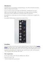
From top to bottom, Ivo's sockets are:
–
Filter cutof CV input
–
Secondary flter cutof CV input, with attenuator
–
Feedback CV input, with attenuator
–
Audio input
–
Secondary audio input, with attenuator
–
Audio output
The two flter cutof inputs are summed; similarly the two audio inputs are summed (mixed).
Controls
In addition to the three attenuators, there is a knob for the cutof frequency (blue) and a knob
for the feedback (yellow).
The switch (marked “poles”) selects between 2-pole (12dB/octave) and 3-pole (18dB/octave)
flter responses.
Calibration
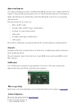
Ivo's cutof frequency response is approximately 1 Volt/octave. The exact scaling can be
adjusted with a trim pot (“RV6”) on the PCB as shown below:
Where to get help
Email, forum, and social media links can be found at the bottom of every page on
Acknowledgments
Black and white photography by
2 https://www.expert-sleepers.co.uk
3 http://israeldenadai.com.br/bw
Содержание Ivo
Страница 1: ...User Manual Revision 1 0 ivo ...


