


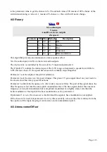


M-3 Logic
A and B are logic outputs
X and Y are inputs
Z selects logical operation for output A
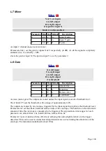
Parameter Min Max Default
Description
0
-2
7
0
Output B logical operation.
1
-100 100 20
Input X threshold.
2
-100 100 20
Input Y threshold.
3
-100 100 10
Input X hysteresis.
4
-100 100 10
Input Y hysteresis.
This algorithm performs logical operations on the X & Y inputs. The inputs first pass through
adjustable comparators, so you can feed X & Y either with straight gate/trigger signals, or with
more general CVs.
X & Y are the inputs. A & B are the outputs, which are 0/5V logical (on/off) signals.
The Z knob/CV sets the logical operation performed for output A; parameter 0 sets the logical
operation performed for output B. The name of the operation selected for output A is shown in the
display as Z changes; the options available are the same as for output B, excluding the -1 and -2
values below:
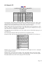
Parameter 0 value
Operation
-2
Output B follows output A
-1
Output B is inverse of output A
0
AND
1
OR
2
XOR
3
NAND
4
NOR
5
XNOR
6
SR flip-flop
7
D flip-flop
The SR flip-flop is set high by a rising edge on input X, and cleared low by a rising edge on input
Y.
The D flip-flop takes the level of input X on a rising edge on input Y.
Parameters 1-4 set the input comparator thresholds and hysteresis (for an explanation of hysteresis
see
). All are scaled such that 100 corresponds to 5V. The input is taken as logical '1' if the
input voltage exceeds the threshold voltage.
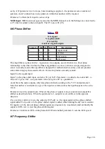
M-4 Half-wave Rectifier
19 http://en.wikipedia.org/wiki/Hysteresis#Electronic_circuits
Page 107


