background image


Experimental Aircraft Models


- 20 -        


WWW.RCHomebuilts.com


If the cowl does not seat fully along the bottom, don’t panic. Much of the bottom is cut 
away for muffler clearance and will ‘widen’ later.  Concentrate on the top and sides to 
have a minimal gap. 


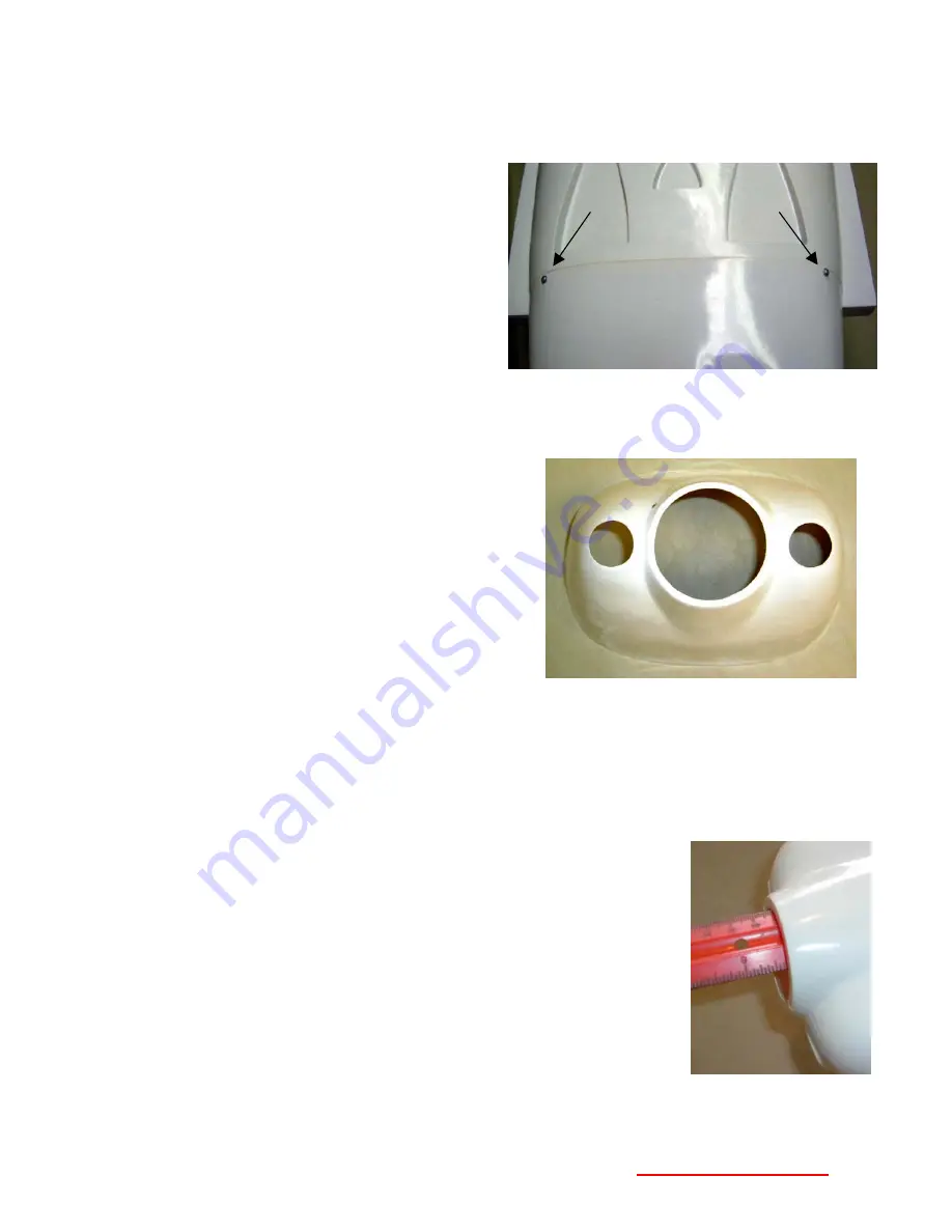
2.  Plan to secure the cowl with four, 2.3 x 

6mm (#2) washer head screws. Decide 
where you want these around the 
circumference of the cowl, and place a 
‘dot’ with a felt tip pen 5/32” (4 mm) aft of 
the ‘joggle’ on the cowl. 

a.  We like about ¼” (6 mm) to the 

outside of each large air inlet and 
about ¼” below the trailing edge of 
the wing fairing.  


3.  When comfortable with the fit, drill a 5/64” (2 mm) hole at each dot,  
 
4.  Install a #2 x3/8” washer head screw in each hole to verify fit. Then remove the cowl.  


5.  Now is a good time to finish the openings in the 

cowl.  A fine rat tail file or flexible shaft tool (e.g. 
Dremel

TM

) with a small milling bit works great.  

We recommend opening the round air outlet 
holes to the outer circumference, flush with the 
surface of the cowl to allow smooth exit flow of 
air.  Also open the large center hole.   Leave 
about 1/8” lip around the circumference for 
support. 


Positioning and Installing the Engine 

 
The objective of this section is to place the engine on the firewall so that the back of the spinner 
clears the rear of the cowl by 1/8” (3mm), and the spinner is centered on the cowl. Our instructions 
will work for all brands of engines.  
 

Positioning the engine fore/aft (front to back) on the motor mount 


1)  Place the cowl on the model and secure with a few screws. 
 
2)  Measure from the firewall to the front edge of the cowl through the 

center opening. It is approximately 5 1/4” (133 mm)  

 
3)  Place the motor mounts on a couple pieces of wood so that the 

engine sits high enough to not bottom out on the bench.  


Содержание Velocity XL

Страница 1: ...sumes or accepts no liability for the manner in which this model aircraft is used by the user in any condition of assembly By the act of purchasing this kit the purchaser and any subsequent user accepts full responsibility and all resulting liability If the purchaser is not willing to accept the above liability associated with the use of this model aircraft the purchaser is advised to return this ...

Страница 2: ...the canopy and fuselage Just as the homebuilder customizes their personal aircraft we have offered the model in pure white so that you may do the same For those unfamiliar with the Velocity XL design the original version came and still does with a fixed tricycle landing gear The retractable gear version was developed a few years later by a customer who later purchased the company Duane Swing We ha...

Страница 3: ...easily be tightened by the application of heat from a hair dryer heat gun or hot iron If using an iron a piece of lightweight cotton e g sheeting placed between the iron and the covering helps to even the heating Pressing lightly will transfer the heat to the covering shrinking the material Piercing a bubble with a pin and rubbing the hot area with a cloth further helps remove the wrinkles Airfram...

Страница 4: ...ng scoop Side of Cowling 1 9 Formed Polished Main Landing Gear Main Landing gear 1 10 8 32 x 1 socket head screw washers Locknuts Main landing gear attachment 4 11 Wheel Pant Set 2 Mains 1 Nose gear 1set 12 3 x 12 mm Phillips screw Wheel Pant Retaining 2 13 4 mm I D x 3 76mm O D Main Wheels 2 14 4 mm I D x 2 3 8 60mm OD Nose Wheel 1 15 4 mm ID collars Main Wheel Retaining 2 16 4 mm ID Nylon spacer...

Страница 5: ...ation 2 set 39 450 CC poly fuel tank Fuel Tank 1 40 Silicon rings Clevis Keepers 8 41 2 mm Allen Key Tighten various set screws 1 42 8 32 Locknuts Washers Landing Gear Attachment 4 43 Nylon Tie wraps Secure Fuel Tank 3 Items needed to Complete Your Velocity Model Your Velocity model flies with a four channel radio However do to the relatively remote location of the rudders one servo is needed to o...

Страница 6: ...direction We have custom Bisson mufflers for the Webra engine which we include in our Firewall Aft Kit and which are available separately Other Stuff CA Adhesive Thin Propane Torch CA Adhesive Medium Solder Flux 30 Minute Epoxy 4 oz min Foam Servo Mounting Tape 5 Minute Epoxy Rubbing Alcohol Building the Wings Installing Aileron Hinges The control surfaces on the wings canard and winglets are not ...

Страница 7: ...site side of the hinge to prevent any excess CA from running down over the wing Check for free movement 8 Repeat steps 1 7 to secure the aileron on the opposite wing 9 Pull on the control surfaces to test their strength Assembling the Winglets We re switching to the winglets rather than finishing up the servo installation for the ailerons because the rudder servo wires run through the aileron serv...

Страница 8: ...self with the activity and objective before starting Slide the winglet over the protruding end of the plate until it is against the wing tip This ensures that the back edge of the plate is fully seated in the recess and that the plate is inserted to the proper point in the winglet On the bottom of the wing use a razor knife and score cut the covering on the bottom of the plate at the surface of th...

Страница 9: ...der pushrod In the other direction the barrel pushes against the spring and allows the pushrod to slide through the barrel as the servo arm rotates towards the winglet Notes You can remove the setscrew in the end of the barrel that normally clamps the rod to the barrel when this part is used to move throttle linkages We will allow the rod to slide through the barrel The servo must be high enough o...

Страница 10: ...djust the linkage so that when the servo is in neutral the inboard collar is pressing against the servo arm and the spring tension keeps the rudder centered Remove the servo arm center screw pull off the servo arm and cut off excess pushrod length Reassemble 7 Test the operation of the rudder with your Transmitter receiver 8 Plug a 36 servo cable extension on to the ruder servo cable Clamp or tape...

Страница 11: ...move Using the point of a razor knife you can carefully lift an edge If you dent the balsa surface re heating the covering will make the dent disappear If there is an adhesive residue it is easily removed with Goo Gone or VMP Naptha 2 Trim the slot opening of each servo cover with a sharp razor knife Don t use the soldering iron trick as it will show the melted edge where it would be visible from ...

Страница 12: ...s for the other wing 10 Plug the servos into the receiver and test their operation to be sure wire connections inside the wing remained tight and the wires are labeled correctly Installing Aileron Horns and Pushrods Nylon control horns will be fastened to the ailerons U S Pack Sullivan 4 Pushrods with metal clevises are sized and then threaded on to the ends of the pushrods with Sullivan Keepers a...

Страница 13: ... fit into the arm Cut the leg to 5 16 6mm 7 Rotate the pushrod back to the correct position and install into the servo arm using a 31 Kwik Keeper 8 Repeat the above steps to install the other aileron servo 9 Finish all servo installations by making sure there is a screw securing the servo arm to the servo and in each of the four corners holding the servo covers in place Canard Assembly The canard ...

Страница 14: ...and 7 8 downward deflection when operating each elevator using the actuating arms Lengthen the notch in the top skin of the canard in which the actuating arm exiting the canard moves if necessary The elevators are intentionally hinged closer to the bottom edge of the elevator to increase their effectiveness so be careful not to install them upside down Some builders like to reinforce the bonding o...

Страница 15: ...tput arms are in place Pre adjust the length of the pushrod arm by screwing or unscrewing the clevis so that both elevators are flush with the surface of the canard 10 Using two sided 1 16 thick adhesive foam servo mounting tape secure the two servos to their plywood mounting platforms Fuselage Assembly Installing the Air Ducts The NACA air inlets on the top of the fuselage are functional to assis...

Страница 16: ...hold in position until the CA sets Turn the fuselage over and apply some thin CA to flow into the joint between the bottom of the duct and the fuselage Mix up a little epoxy and dab into the seam between the duct and the NACA vent to support the front edge 8 Trim the excess length flush with the firewall 9 Repeat for the remaining two inlets Reinforcing the Bond of the Interior Frames The bonding ...

Страница 17: ...teering servo mount with the epoxy mix to ensure good bonding of these notched pieces Congratulations You ve just done a technique of reinforcing corner joints with flox and glass tape that is identical to the way it s done on the full scale Velocity Painting the Fuselage Your Velocity model was intentionally supplied in all white so that you can customize it If you d like to paint the fuselage be...

Страница 18: ...n the catalyzed Nelson paints we recommend a top coat of Minwax Clear Acrylic Urethane for glo fuel protection Engine Fuel Tank Installation Additional components you may need from the hobby store We offer a special Bisson pusher muffler for the Webra Speed 1 20 engine If you fit a normal Pitts style muffler the exhaust stacks will point forward into the slip stream If you are installing a four st...

Страница 19: ...rm has slots in it Position the fuel tank between the slots with the inlet outlet tube pointing to the left with the EAM at the bottom This will point the tank forward and have the fuel pick ups at the rear of the tank where the forward motion of the airplane will tend to push the fuel Do not point the tank in the other direction to shorten the fuel lines Trust us we have the pieces uh experience ...

Страница 20: ...the cowl A fine rat tail file or flexible shaft tool e g DremelTM with a small milling bit works great We recommend opening the round air outlet holes to the outer circumference flush with the surface of the cowl to allow smooth exit flow of air Also open the large center hole Leave about 1 8 lip around the circumference for support Positioning and Installing the Engine The objective of this secti...

Страница 21: ...unts as opposed to measuring That is we ll put the engine mounts assembly under the cowl position it and mark the location This is easier with a second set of hands First test that the back plate for the aluminum spinner slips over the prop shaft be sure it s a close fit and easily removed A bushing is packed with the spinner nut Then read 1 through 10 below before starting 1 Remove the cowl and s...

Страница 22: ...he outside of the barrel of a blind nut insert the blind nut from the inside of the fuselage using inside out masking tape on the end of your finger is a good trick into the hole and pull tight with the screw against the washer Remove the screw and washer and repeat for the remaining three blind nuts 8 Cut a piece of fuel line 24 530mm for the Webra pumped engine otherwise check the length with yo...

Страница 23: ...l tube of the tank and the DuBro Fill It Fuel System Dot previously installed The extra length is so you can easily pull the dot out to fill the tank When the tank it full it will pee out the vent tube under the model Nose Gear Installation During the development of the Velocity model we opted to supply a more expensive non scale double strut nose gear There were two reasons for this 1 A canard ai...

Страница 24: ...r can be inserted into the nylon housing through the bottom of the aircraft in line with the pivot hole in the bracket Note that the entire brass barrel will be inside the fuselage leaving only the wire portion extending from the bottom The hole needs to be no larger than to fit the brass piece into the bottom Temporarily remove the brass nut to allow it to fit in a minimal size hole just under 5 ...

Страница 25: ...ng gear 9 Axle set 17 Main Wheels 13 wheel retaining Collars 15 Wheel Pant Retaining Screws 12 and main Wheel Pants 11 2 When installed the landing gear sweeps forward Fit the recess molded into each wheel pant to the correct end of the landing gear and mark the location of the main axle hole and smaller retaining hole Our manual model needed the ends of the gear trimmed to the correct angle Make ...

Страница 26: ...inst the lip of the recess This will give you the most amount of room for nut clearance of the frame inside the fuselage Line up the centerline marks and mark the location of the mounting holes Drill the holes 11 64 dia 4 5mm 12 Secure the landing gear using four 8 32 x 1 Socket Head screws 10 and four locknuts and washers 42 If clearance is a problem for the nut with the interior frame reverse th...

Страница 27: ...f you leave the top one off and secure with Loctite or similar thread locker Set aside This part rotates as the arm moves so the nut must not be tight but close and prevented from loosening 2 Install the servo with the mounting hardware supplied by the radio manufacturer Position the servo with the output shaft oriented towards the centerline of the aircraft 3 Retrieve the throttle pushrod Approx ...

Страница 28: ...e Rudder output of the receiver and temporarily connect one rudder servo on a winglet and the steering servo to the other leg of the Y Check that the rudder servo is electrically centered which will drive the steering servo to the centered position also Switch the radio off receiver first 3 Secure the steering servo using the mounting hardware supplied by the radio manufacturer 4 Slip the steering...

Страница 29: ...l plug the ends of the aileron extensions Which will also enter the fuselage from the sides aft of the cockpit along with the rudder wires 6 Plug the throttle servo into the 6 extension 7 Temporarily install the canard using four 4 40 x 1 socket head bolts 25 Drill file a clearance hole in the fuselage above the trailing edge for the elevator servo wires to enter Look from the inside of the fusela...

Страница 30: ...sing Velcro Tie Wraps adhesive backed wire tie anchors etc Just remember that it has a certain amount of mass and you don t want it coming loose in the cockpit during your no doubt perfectly coordinated ball centered aerobatic routines Canard Cover Fitting 1 Retrieve the canard cover and epoxy the latch arm covers 32 in place Be careful that you don t get epoxy into the latches or bond them to the...

Страница 31: ...ion of the wing around the aluminum carry through not have the nylon bolts to do that Oversize holes in the vertical direction would allow rotation 4 Retrieve the four 20 x 2 Nylon Finger Bolts Measure from the base of the flange and cut them to 1 25 mm An easy way to do this is to snip them with a pair of diagonal wire cutters no thread clean up will be needed 5 Test fit the bolts into the wings ...

Страница 32: ...n around the outside edge ii Using the side of a razor knife to shave the edge of the part is a great way to also smooth the edge and remove any hanging on excess from sanding 3 Place the inlet against the cowl in the desired position and mark trace around the outside of the scoop a If you re placing the inlet beneath the wing to cool the lower half of the cylinder place it as high as possible wit...

Страница 33: ...ate the canopy is molded from is slightly tinted so painting the inside will result and an off color non match We have supplied computer cut window masks which you can lay in place to simplify this step P As mentioned previously we suggest using either Krylon Fusion or Rustoleum plastic primer paint The Rustoleum covers well Both will benefit from a clear top coat of Minwax clear Acrylic Urethane ...

Страница 34: ...rekote painting tips topr7200tip1 html In a nutshell the process is to scuff sand the film with 00 steel wool so that a mechanical bond can be made to the film A primer may be applied and then the top coat They recommend the use of their Lustrekote paints which have been tested for adhesion and glo fuel resistance but you can also use the paints and top coat discussed above If you are not modeling...

Страница 35: ... then loaded lead shot in baggies through the hatch and stuffed foam to hold in place We then taped the hatch back in place Alternatively you can mix up a slurry of lead shot and epoxy and pour it into the nose cone by standing the model on its nose and pouring in through the openings in the nose gear bulkhead Bench Pre Flight In case we didn t mention it before Make sure all clevises have their s...

Отзывы: