Maintenance
1.
Stop engine and wait for all moving parts to stop.
Engage parking brake. Remove key or spark plug
wire(s).
2.
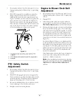
With PTO engaged (lever pulled up, adjust the
linkage length to where the lower end of the
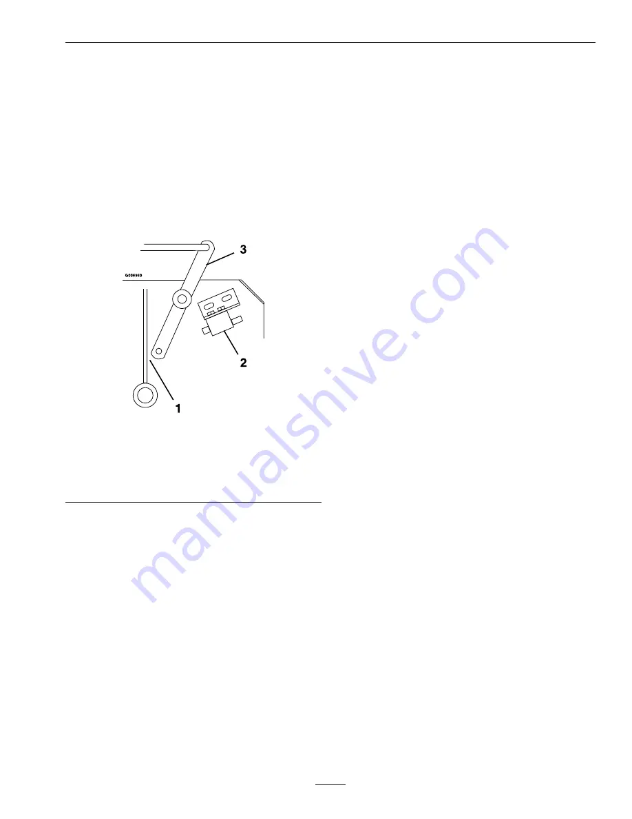
bellcrank just clears the axle support gusset (see
Figure 12). Make sure the assist arm is against the
rear assist arm stop on the deck (see Figure 13).
Push the lever down to the disengaged position.
The assist arm should contact the front assist arm
stop on the deck. If it does not contact, readjust
so that the bellcrank is closer to the gusset.
g006960
Figure 12
1.
The bellcrank just clears the gusset with the PTO
engaged
2.
PTO Safety Switch (located beneath the engine deck)
3.
Bellcrank
PTO Safety Switch
Adjustment
1.
Stop engine and wait for all moving parts to stop.
Engage parking brake. Remove key or spark plug
wire(s).
2.
With PTO disengaged and assist arm against the
front assist arm stop, adjust the blade safety switch
mounting bracket (if needed) until the bellcrank
depresses the plunger by 1/4 inch (.64 cm).
3.
Be sure the bellcrank Does Not touch the switch
body or damage to the switch could occur.
4.
Retighten switch mounting bracket.
Engine to Mower Deck Belt
Adjustment
1.
Stop engine and wait for all moving parts to stop.
Engage parking brake. Remove key or spark plug
wire(s).
2.
Engage PTO.
3.
Check belt guides under rear engine and front
mower deck to see that they are properly set (see
Belt Guide Adjustment
section for instructions).
4.
Belt must be tight enough so it does not slip during
heavy loads while cutting grass. Over-tensioning
will reduce belt and spindle bearing life. To adjust
belt tension, loosen the 5/16 inch whizlock nut
on turnbuckle and rotate the turn buckle; rotate
turnbuckle toward rear of mower to tighten, and
toward front of mower to loosen belt tension (see
Figure 13).
For 48 inch Decks: If there is no adjustment left
in the turnbuckle and the belt is still loose, the rear
idler pulley can be repositioned in the front hole
(see Figure 13). The belt guide located next to the
pulley must also be repositioned in the front hole
when the pulley is moved. The turnbuckle will
need to be readjusted.
Check belt tension after the first hour of operation
and at least twice during the first 24 hours of
operation. Adjust as necessary.
Note:
After readjusting the belt tension check the
belt guide adjustment as stated in the
Belt Guide
Adjustment
and
Blade Brake Adjustment
sections.
35
Содержание VIKING 346
Страница 1: ...VIKING For Serial Nos 408 644 346 Higher Part No 4505 182 Rev A ...
Страница 45: ...Schematics g010189 45 ...
Страница 47: ...47 ...

