Operation
Choke Control
Located on the front control console right of the
PTO engagement switch.
The choke is used to aid in starting a cold engine.
Moving the choke lever forward will put the choke in
the “ON” position and moving the choke lever to the
rear, to the detent, will put the choke in the “OFF”
position. Do Not run a warm engine with choke in
the “ON” position.
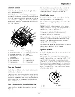
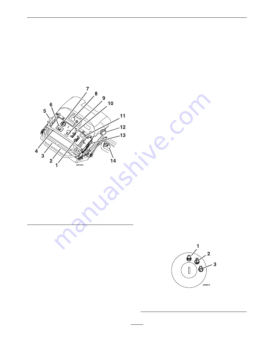
Figure 5
1.
Choke
8.
Fuel gauge
2.
RH Motion control lever
9.
PTO engagement switch
3.
LH Motion control lever
10.
Throttle
4.
Front Reference/Speed
Control Bar
11.
Deck lift handle
5.
Park brake lever
12.
Fuel cap
6.
Message display
13.
Height-of-cut pin
7.
Ignition switch
14.
Platform latch
Throttle Control
Located on the RH side of the front control console
(red lever) (see Figure 5).
The throttle is used to control engine speed. Moving
the throttle lever forward will increase engine speed
and moving the throttle lever to the rear will decrease
engine speed. Moving the throttle forward into the
detent is full throttle.
Front Reference/Speed Control Bar
Located in front of the motion control levers (see
Figure 5).
The front reference/speed control bar controls the
maximum forward speed and is infinitely variable
from approximately 4–8 mph (6–13 km/hr).
Park Brake Lever
Located on left side of unit, just to the front of the
LH motion control lever (see Figure 5).
The brake lever engages a parking brake on the drive
wheels.
Note:
The LCD indicator appears in the message
display on the front console when the park brake is
engaged (see Figure 5 and Figure 7).
To engage the brake, pull the lever rearward.
To release, push the lever forward.
When parking on a steep slope, the wheels must be
chocked or blocked in addition to the brake being
engaged. The unit must be tied down and brake
engaged when transporting.
Park brake must be disengaged before moving motion
control out of neutral or engine will kill.
Ignition Switch
Located on the LH side of the front control console
(see Figure 5).
The ignition switch is used to start and stop the
engine. The switch has three positions “OFF”, “ON”
and “START”. Insert key into switch and rotate
clockwise to the “ON” position. Rotate clockwise to
the next position to engage the starter (key must be
held against spring pressure in this position). Allow
the key to return to the “ON” position immediately
after the engine starts.
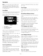
Figure 6
1.
Off
3.
Start
2.
On
17
Содержание VANTAGE S Series
Страница 1: ...VANTAGE S SERIES 36 INCH MODELS For Serial Nos 316 000 000 Higher Part No 4502 635 Rev A ...
Страница 46: ...Schematics Schematics Electrical Diagram 46 ...
Страница 47: ...Schematics Electrical Schematic 47 ...
Страница 48: ...Schematics Hydraulic Diagram 48 ...
Страница 50: ...50 ...

