background image


- 35 -

7. WASTE DISPOSAL 


7.1  MOTOR OIL DISPOSAL. 


Engine oil and hydraulic oil are both pollutants to the environment.  Dispose of used oil 
at a certified recycling center or according to your state and local regulations. 

 7.2 

BATTERY 

DISPOSAL


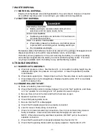
DANGER 

POTENTIAL HAZARD 

  Battery electrolyte contains sulfuric acid, which is 

poisonous and can cause severe burns 

WHAT CAN HAPPEN 

  Swallowing electrolyte can be fatal or if it touches skin 

can cause severe burns. 

HOW TO AVOID THE HAZARD 

  Wear safety glasses to shield eyes, and rubber gloves 

to protect skin and clothing when handling electrolyte. 

  Do not swallow electrolyte. 


Federal law states that batteries should not be placed in the garbage.  Management and 
disposal practices must be within relevant federal, state, or local laws. 


If a battery is being replaced or if the unit containing the battery is no longer operating 
and is being scrapped, take the battery to a local certified recycling center.  If no local 
recycling is available return the battery to any certified battery reseller. 

8. TROUBLE SHOOTING 

  8.1  MOWER CUTS UNEVENLY. 


a)  Check air pressure in tires.  See Section 2.8.  A more uniform cutting height may be 

obtained with higher tire pressure on rough terrain.  A lower tire pressure provides 
more flotation. 


b)  Check deck support pins.  Hairpin clips must be in the same hole on each support pin. 


c)  Check blades tip to tip for straightness.  Blades should be within 3/16” or one blade 

width from being in line.   


  8.2  ENGINE WILL NOT START. 


a)  Make sure battery has a full charge. 


b)  Check that throttle control is midway between “slow” and “fast” positions, and choke 

is in “on” position for a cold engine or “off” position for a warm engine. 


c)  Be sure there is fuel in the tank and that the fuel valve is open. 


d)  Operator must be in the seat. 


e)  Check that parking brake is set. 


f)  Be sure that the PTO is disengaged. 


g)  Check that the spark plug wires are properly connected. 


h)  Look for loose or faulty wiring connections. 


i)  Check for corrosion at all wiring connections.  Even minor corrosion may cause a 

faulty connection.  Clean connector terminals thoroughly and reconnect. 


NOTE:  When disconnecting electrical connectors, DO NOT pull on the wires to 
separate connectors. 


j)  Check that the seat switch is properly adjusted. See Section 6.2.12. 


k)  Check that the parking brake switch is properly adjusted.  See Section 6.2.10. 

Содержание Turf Ranger TR23KC

Страница 1: ...For Turf Ranger Serial Nos 510 000 Higher and FMD524 FMD604 Serial Nos 510 000 Higher Part No 103 9192 ...

Страница 2: ...rom eyes and skin Never siphon by mouth IMPORTANT When the mower is used or operated on any California forest brush or grass covered land a working spark arrester must be attached to the muffler If not the operator is violating state law Section 4442 Public Resource Code To acquire a spark arrester for your unit see your Engine Service Dealer This spark ignition system complies with Canadian ICES ...

Страница 3: ...bmitting the Exmark Parts Plus order to Exmark by 3 00 p m central time the Distributor pays for the part and freight 3 Exmark being unable to ship the part and the Exmark parts order is received by 3 00 p m central time Exmark pays for the part and freight 4 If the part does not arrive overnight due to the shipper UPS the shipper pays for the freight and Exmark pays for the part The following res...

Страница 4: ...wer maintain its maximum efficiency and promote safe operation If additional information is needed or should you require trained mechanic service contact your authorized Exmark equipment dealer or distributor All Exmark equipment dealers and distributors are kept informed of the latest methods of servicing and are equipped to provide prompt and efficient service in the field or at their service st...

Страница 5: ...ic Ground Drive System 10 2 8 Tires 11 2 9 Deck 11 2 10 Dimensions 11 2 11 Torque Requirements 11 3 ASSEMBLY INSTRUCTIONS 3 1 to 3 10 Assembly 12 15 4 CONTROLS 15 17 5 OPERATION INSTRUCTIONS 5 1 Pre Start 17 5 2 Mowing 17 18 5 3 Transporting 18 19 6 MAINTENANCE ADJUSTMENTS 6 1 Periodic Maintenance 19 27 6 2 Adjustments 27 33 7 WASTE DISPOSAL 7 1 Motor Oil Disposal 34 7 2 Battery Disposal 34 8 TROU...

Страница 6: ...perator s or mechanic s can not read English it is the owner s responsibility to explain this material to them 1 2 3 Do not allow operation of this machine by untrained personnel Never allow children teenagers or people unfamiliar with these instructions to use the mower Local regulations may restrict the age of the operator 1 2 4 Avoid mowing while people especially children or pets are nearby Ke...

Страница 7: ... or explosion from gasoline can burn you others and cause property damage HOW TO AVOID THE HAZARD DO NOT smoke while refueling and stay away from an open flame or where gasoline fumes may be ignited by spark Refuel only outdoors Store gasoline in an approved container and keep it out of the reach of children Add fuel before starting the engine Never remove the cap of the fuel tank or add fuel when...

Страница 8: ...e then refuel such equipment on a truck or trailer from a portable container rather than from a gasoline dispenser nozzle If a gasoline dispenser nozzle must be used keep the nozzle in contact with the rim of the fuel tank or container opening at all times until fueling is complete WARNING POTENTIAL HAZARD Gasoline vapor can collect inside enclosed trailers and may be ignited by electrical sparks ...

Страница 9: ...maintain in working order a spark arrester before using equipment on forest covered grass covered or brush covered unimproved land WARNING POTENTIAL HAZARD Hands feet hair clothing or accessories can become entangled in rotating parts WHAT CAN HAPPEN Contact with rotating parts can cause traumatic amputation or severe lacerations HOW TO AVOID THE HAZARD Do not operate the machine without guards sh...

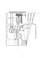
Страница 10: ... or water This area can be dangerous see Figure 1 Figure 1 SAFE ZONE FOR MOWING Progressively greater care is needed as the slope increases Always avoid sudden starts and turns Be aware that loss of traction may occur going downhill Weight transfer to the front wheels may cause rear wheel to lift off ground cause loss of steering Watch for ditches holes rocks dips and rises that change the operati...

Страница 11: ... positions Allow the engine to run a minimum of 15 seconds then stop the engine 1 4 15 The fuel system is provided with a shut off valve The fuel shut off valve is used to shut off the fuel when a The machine will not be used for a few days b During transport to and from the job c When parking inside a building 1 4 16 This mower was designed for one operator only Keep all others away from mower du...

Страница 12: ...ed in a basement or any enclosed area where open pilot lights or heat appliances are present 1 5 8 Maximum mowing results and safety can only be achieved if the mower is properly maintained and operated correctly 1 5 9 Check all bolts frequently to maintain proper tightness 1 5 10 Keep all guards shields and all safety devices in place and in safe working condition 1 5 11 Frequently check for worn...

Страница 13: ...rface Smooth to remove any air bubbles 1 6 6 Familiarize yourself with the following safety signs and instruction labels They are critical to the safe operation of your Exmark commercial mower PART NO 1 513747 LOCATION Top Front of Battery Cover FMD524 FMD604 units only PART NO 103 2239 LOCATION Top of Mower Deck Beneath Center Shield PART NO 103 2432 LOCATION Left Side of Brake Lever PART NO 1 54...

Страница 14: ...ace of Mower Deck PART NO 1 543620 LOCATION On Intake Screen Below Fuel Tank PART NO 1 543896 LOCATION Under Engine Deck on Wood Blocks for Shipping PART NO 98 5954 LOCATION Under Belt Shields Type A Anti Scalp Rollers Only See Figure 7 PART NO 1 323540 LOCATION Front of Mower Deck Top Surface ...

Страница 15: ...th little effort Motion control pedal and linkages are protected by the motion override device when the parking brake is engaged 2 5 3 Parking Brake Lever Engages park brake and locks drive system in neutral Neutral lockout system prevents accidental engagement of drive system when park brake is engaged and protects hydro transaxle from potential damage 2 6 SEAT 2 6 1 Type high back foam padded in...

Страница 16: ...MENSIONS 2 10 1 Overall Width without deck deflector up deflector down Turf Ranger with FMD524 49 9 126 8 cm 53 4 135 6 cm 64 2 163 1 cm Turf Ranger with FMD604 49 9 126 8 cm 61 4 156 0 cm 72 2 183 4 cm 2 10 2 Overall Length without deck with deck Turf Ranger with FMD524 70 2 178 3 cm 112 4 285 5 cm Turf Ranger with FMD604 70 2 178 3 cm 112 4 285 5 cm 2 10 3 Curb Weight Turf Ranger with FMD524 931...

Страница 17: ... less to avoid damaging the battery see chart below for recommended charger settings Voltage Reading Percent Charge Maximum Charger Settings Charging Interval 12 6 or greater 100 16 volts 7 amps No Charging Required 12 4 12 6 75 100 16 volts 7 amps 30 Minutes 12 2 12 4 50 75 16 volts 7 amps 1 Hour 12 0 12 2 25 50 14 4 volts 4 amps 2 Hours 11 7 12 0 0 25 14 4 volts 4 amps 3 Hours 11 7 or less 0 14 ...

Страница 18: ... 1 1 4 bolts and two 3 8 spring disc washers 3 7 INSTALL CANISTER AIR CLEANER a Remove air cleaner with bracket attached from crate Keep air cleaner and mounting bracket together b Cut plastic tie holding air cleaner cap to engine and install cap to the air cleaner c Remove the top two throttle plate mounting screws from the engine Keep screws for re attaching air cleaner d Position the air cleane...

Страница 19: ...ower deck support frame in place over the mower deck Align support frame above mower deck and position it so the support pins on the deck align with the mounting holes in the support frame Lower support frame onto deck and Reinstall the two hairpins and spacers on the front support pins and the two hairpins and spacers onto the rear support pins See Figure 1 3 8 5 After the mower deck support fram...

Страница 20: ...CHUTE Loosen two 2 5 16 nyloc nuts attaching discharge chute Lower the discharge chute into position Retighten nyloc nuts until chute is snug but can pivot freely 3 10 SERVICE ENGINE See Engine Operator s Manual 4 CONTROLS Familiarize yourself with all controls before operating the mower 4 1 Steering Handle Bar Located in center of steering console in front of operator s seat During forward operat...

Страница 21: ...brake is disengaged or engine will stop 4 8 Ignition Switch Located on the control console just ahead of the steering handle The ignition switch is used to start and stop the engine The switch has three positions OFF ON and START Insert key into switch and rotate to the right to the ON position Rotate clockwise to the next position to engage the starter key must be held against spring pressure in ...

Страница 22: ...e steps 5 2 MOWING 5 2 1 Starting Engine Operator must be in the seat with the parking brake engaged and the PTO disengaged Open fuel shut off value On a cold engine place the throttle midway between the SLOW and FAST positions and place the choke in the ON position On a warm engine place the throttle midway between the SLOW and FAST positions and leave the choke in the OFF position Turn ignition ...

Страница 23: ...gaging the PTO IMPORTANT Operator must be in seat before the PTO can be engaged Set throttle to midway position The switch must be pulled out to the ROTATE position to engage the blades Accelerate to full throttle to begin mowing 5 2 4 Stopping PTO Set throttle to idle position Push in on the switch to the STOP position to stop the blades 5 3 TRANSPORTING 5 3 1 Transporting a Unit Use a heavy duty...

Страница 24: ... laws and the operator may be subject to traffic tickets and or fines HOW TO AVOID THE HAZARD Do not drive a unit on a public street or roadway 6 MAINTENANCE ADJUSTMENTS WARNING POTENTIAL HAZARD While maintenance or adjustments are being made someone could start the engine WHAT CAN HAPPEN Accidental starting of the engine could seriously injure you or other bystanders HOW TO AVOID THE HAZARD Remov...

Страница 25: ...from engine air intake screen and from around engine shrouding 6 1 3 Clean transmission cooling compartment Service Interval Daily a Stop engine wait for all moving parts to stop and remove key b Clean all debris from screens that encompass cooling compartment and then remove the compartment screen c Clean all debris from the fan blades and the cooling fins for the transmission d Replace the compa...

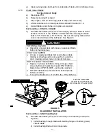
Страница 26: ...g a mower deck with loose or weakened blade bolts can be dangerous WHAT CAN HAPPEN A loose or weakened blade bolt could allow a blade rotating at a high speed to come out from under the deck causing serious injury or property damage HOW TO AVOID THE HAZARD Replace the blade bolt after striking a foreign object Use only Exmark replacement parts PN 103 0862 blade bolt and PN 103 0865 spring disc was...

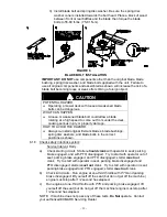
Страница 27: ...ll original Exmark blades blade bushings spring disc washers and blade bolts in the correct positions as shown 6 1 6 Check safety interlock system Service Interval Daily a Check starting circuit Starter should crank with operator in seat parking brake engaged and with PTO disengaged Try to start with operator out of seat parking brake engaged and PTO disengaged starter must not crank Try to start ...

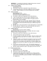
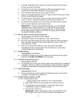
Страница 28: ... 1 9 Change engine oil Service Interval See Engine Owner s Manual NOTE Change oil after first five 5 hours of operation then refer to engine manual for future oil change frequencies a Stop engine wait for all moving parts to stop and remove key b Drain oil while engine is warm from operation c Oil drain is located on the left side of the engine Place pan under machine to catch oil and open valve w...

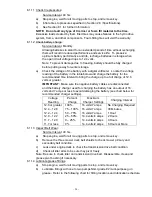
Страница 29: ... of 12 6 volts or greater IMPORTANT Make sure the negative battery cables are disconnected and the battery charger used for charging the battery has an output of 16 volts and 7 amps or less to avoid damaging the battery see chart below for recommended charger settings Voltage Reading Percent Charge Maximum Charger Settings Charging Interval 12 6 or greater 100 16 volts 7 amps No Charging Required ...

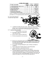
Страница 30: ...nterval Once Yearly a Stop engine wait for all moving parts to stop and remove key b Remove caster wheel from caster forks c Remove seal guards from the wheel hub d Remove one of the spacer nuts from the axle assembly in the caster wheel Note that thread locking adhesive has been applied to lock the spacer nuts to the axle Remove the axle with the other spacer nut still assembled to it from the wh...

Страница 31: ...nd clean cooling fins Also clean dust dirt and oil from external surfaces of engine which can cause improper cooling c Make sure cooling shroud cleanout covers are properly reinstalled Operating the engine without cooling shroud cleanout covers will cause engine damage due to overheating 6 1 17 Change fuel filter Service Interval As Required a A fuel filter is installed in the fuel line between th...

Страница 32: ...t Electric clutch gap Service Interval 250 hrs Refer to Section 6 2 12 for inspection and adjustment procedures 6 1 22 Refer to the Engine Owner s Manual for detailed maintenance required for servicing the engine 6 1 23 Wheel hub slotted nut torque specification a Tighten the slotted nut on the transaxle tapered shaft and torque to 100 ft lbs b After proper torque has been applied turn the nut unt...

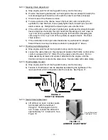
Страница 33: ...ved a Stop engine and wait for all moving parts to stop b Install hairpin clips in the holes for the desired cutting height See Figure 10 IMPORTANT To maintain correct cutting height and rake check the following for proper adjustment 1 The front and rear hairpins are in the same holes with the proper spacers under the hair pins See Figure 8 2 The tire pressures are set as directed in Section 6 1 1...

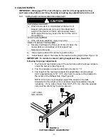
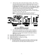
Страница 34: ... lbs 54 61 N m Type B Torque the 3 8 nyloc nut to 30 35 ft lbs 41 47 N m Torque the 3 8 24x2 Gr 8 hex capscrew to 50 55 ft lbs 68 75 N m FIGURE 9 ANTI SCALP ROLLER INSTALLATION AND CUTTING HEIGHT ADJUSTMENT d When operating in extremely rough conditions it may be necessary to position the anti scalp rollers one or two holes higher than described in c to prevent damage to the rollers and or bolt fa...

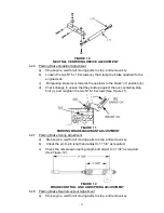
Страница 35: ...ove the electrical connection from the parking brake safety switch located on the right hand underside at the front of the engine deck Temporarily install a jumper wire across the terminals in the connector of the wiring harness c Release brake lever d The Neutral Centering Device is located on the right hand underside of the engine deck Loosen jam nut d from the ball joint which connects the over...

Страница 36: ...butt up against the over centering stop bolt c and retighten the two 5 16 18 screws See Figure 11 FIGURE 11 PARKING BRAKE QUADRANT ADJUSTMENT 6 2 7 Parking Brake Spring Adjustment a Stop engine wait for all moving parts to stop and remove key b Check the pin to pin length and adjust to 11 5 8 as required c Check the compression spring length and adjust to 3 1 32 as required See Figure 12 FIGURE 12...

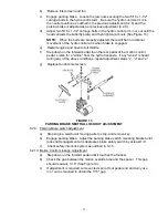
Страница 37: ...ar pedal of the motion control pedal Listen for a whine from the hydro transaxle If any whine is heard during any of the above conditions repeat adjustment steps c d and e g Replace fan and inlet screen FIGURE 13 PARKING BRAKE NEUTRAL LOCKOUT ADJUSTMENT 6 2 9 Parking brake switch adjustment a Stop engine wait for all moving parts to stop and remove key b Engage parking brake Adjust the parking bra...

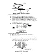
Страница 38: ...hten the top nut Recheck the measurement and adjust again if necessary d Check safety interlock system as outlined in 6 1 6 FIGURE 15 SEAT SWITCH ADJUSTMENT 6 2 12 Electric Clutch Adjustment a Stop engine wait for all moving parts to stop and remove key b Engage parking brake c Place 015 021 inch feeler gauge through each of the three clutch gap holes If gap exceeds this range tighten the three ad...

Страница 39: ...rn right when handle bar is positioned for straight forward travel reverse procedure as stated in paragraph d above 6 2 14 Throttle Control Adjustment a Stop engine wait for all moving parts to stop and remove key b Loosen the cable clamp on the engine and position the throttle control at the control console within 1 4 6mm from the upper end of the slot Pull on cable assembly at lower end where it...

Страница 40: ...LY a Check air pressure in tires See Section 2 8 A more uniform cutting height may be obtained with higher tire pressure on rough terrain A lower tire pressure provides more flotation b Check deck support pins Hairpin clips must be in the same hole on each support pin c Check blades tip to tip for straightness Blades should be within 3 16 or one blade width from being in line 8 2 ENGINE WILL NOT S...

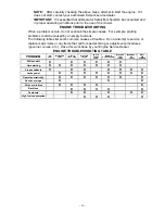
Страница 41: ...common causes of troubles Do not attempt to service or replace major items or any items that call for special timing or adjustment procedures governor valves etc Have this work done by your Engine Service Dealer ENGINE TROUBLESHOOTING TABLE PROBLEM NO FUEL IMPROPER FUEL DIRT IN FUEL LINE DIRTY AIR FILTER FAULTY SPARK PLUG ENGINE OVERLOADED BLOCKED FUEL FILTER INCORRECT OIL LEVEL DIRTY AIR SCREEN W...

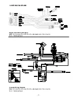
Страница 42: ...ne Deck Wiring Diagram Note All connectors are viewed from the wire input side of the connector N O Normally Open Console Wiring Diagram Note All connectors are viewed from the wire input side of the connector N O Normally Open ...

Страница 43: ...with the Service Dealer s analysis or with the assistance provided contact us at Exmark Customer Service Department The Exmark Warranty Company 2101 Ashland Avenue Beatrice NE 68310 402 223 6375 or service exmark com Owner s Responsibilities The Exmark turf equipment including any defective part must be returned to an authorized Exmark service dealer within the warranty period This warranty extend...

Страница 44: ... 38 NOTES ...

Страница 45: ... 38 NOTES ...

Страница 46: ... 39 SERVICE RECORD Date Description of Work Done Service Done By ...

Страница 47: ... 40 ...

Страница 48: ...UICK DISPOSAL SYSTEM WALK BEHIND ACCESSORIES GRASS CATCHER MICRO MULCH SYSTEM STEERABLE SULKY SULKY HITCH KIT TURF STRIPER WARNING The engine exhaust from this product contains chemicals known to the State of California to cause cancer birth defects or other reproductive harm 1997 2005 PART NO 103 9192 EXMARK MFG CO INC 402 223 6300 INDUSTRIAL PARK BOX 808 FAX 402 223 5489 BEATRICE NE 68310 ALL RI...

Отзывы: