Maintenance
1.
Drive the machine onto a level surface.
2.
Disengage the blade control switch (PTO), move
the motion control levers to the neutral locked
position and set the parking brake.
3.
Stop the engine, wait for all moving parts to stop,
and remove the key.
4.
Setup the machine to be pushed by hand (see
Drive Wheel Release Valves
in the Operation
section).
5.
Raise the back of the machine up and support the
machine with jack stands.
6.
Engage/disengage the brake and check each drive
tire to make sure each brake engages/disengages.
7.
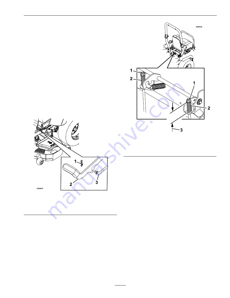
If adjustment is necessary, disengage the park
brake. Remove cotter pin from the brake linkage
shaft (see Figure 72).
g035879
Figure 72
1.
Cotter pin
3.
Brake linkage shaft
2.
Parking brake
8.
Check both spring lengths as shown in Figure 73.
If adjustment is necessary, turn the top nut
clockwise to shorten and counterclockwise to
lengthen.
g036100
Figure 73
1.
Top nut
3.
1.75 inches (44 mm)
2.
Spring
9.
Push the parking brake lever all the way forward
and down. Rotate the brake linkage shaft until the
end aligns with hole in lever.
•
Shorten the linkage by turning it clockwise.
•
Lengthen the linkage by turning it
counterclockwise.
Insert the brake linkage shaft into parking brake
hole and secure with the cotter pin. Repeat step 6
and readjust if necessary.
10.
When adjustment is complete, remove the jack
stands or equivalent support and lower the
machine.
11.
Place the machine into the “operating” position.
Refer to the
Drive Wheel Release Valves
section
in Operation.
Motion Control Handle
Adjustment
Adjusting the height:
69
Содержание Radius E Series
Страница 1: ...RADIUS For Serial Nos 408 644 346 Higher Part No 4505 549 Rev A ...
Страница 76: ...Schematics Schematics Electrical Logic Schematic Exmark Engine g036150 76 ...
Страница 80: ...Notes 80 ...
Страница 81: ...Service Record Date Description of Work Done Service Done By 81 ...
Страница 82: ...82 ...


