background image

Product Overview

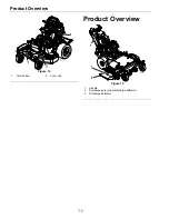
Figure 14

1.

Velcro strap

2.

Loom clip

Product Overview

Figure 15

1.

Handle

2.

Discharge gate (under discharge deflector)

3.

Discharge deflector

12

Содержание OCDWB01 Operators

Страница 1: ...OCDWB01 OPERATOR CONTROLLED DISCHARGE FOR WALK BEHIND UNITS Part No 4500 569 Rev A ...

Страница 2: ...ctured previously Exmark or its distributors and dealers accept no responsibility for variations which may be evident in the actual specifications of its products and the statements and descriptions contained in this publication 2010 Exmark Mfg Co Inc Industrial Park Box 808 Beatrice NE 68310 2 Contact us at www Exmark com Printed in the USA All Rights Reserved ...

Страница 3: ...u require trained mechanic service contact your authorized Exmark equipment dealer or distributor Exmark parts manuals are available online at http www exmark com manuals htm All Exmark equipment dealers and distributors are kept informed of the latest methods of servicing and are equipped to provide prompt and efficient service in the field or at their service stations They carry ample stock of s...

Страница 4: ...stalling OCDWB01 on Mower Deck 8 Product Overview 12 Operation 13 Opening the Discharge Gate 13 Closing the Discharge Gate 14 Removing the OCDWB01 14 Maintenance 16 Recommended Maintenance Schedule s 16 Periodic Maintenance 16 Check for Loose Hardware 16 Check Discharge Gate Closure 16 Adjustments 16 Handle Adjustment 16 Discharge Gate Adjustment 17 Troubleshooting 18 4 ...

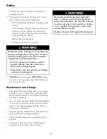
Страница 5: ...sponsible for training the users Never let children or untrained people operate or service the equipment Local regulations may restrict the age of the operator Only adults and mature teenagers should operate a mower and even mature teenagers should have adult supervision Be sure a teenager 1 has read and understands the Operator s Manual and recognizes the risks involved 2 is sufficiently mature t...

Страница 6: ...ER carry passengers DO NOT operate the mower when people especially children or pets are in the area Maintenance and Storage Disengage PTO set parking brake stop engine and remove key or disconnect spark plug wire Wait for all movement to stop before adjusting cleaning or repairing Use care when checking blades Wrap the blade s or wear gloves and use caution when servicing them Only replace damage...

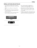
Страница 7: ...achment or accessory has been installed make sure current safety signs are visible New safety signs may be obtained from your authorized Exmark equipment dealer or distributor or from Exmark Mfg Co Inc Safety signs may be affixed by peeling off the backing to expose the adhesive surface Apply only to a clean dry surface Smooth to remove any air bubbles Familiarize yourself with the following safet...

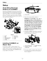
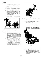
Страница 8: ...the OCDWB01 frame to fit properly to these decks Figure 3 1 Knock out tab 1 Flip up the existing discharge deflector Important The OCDWB01 comes with its own discharge deflector When using the OCDWB01 Exmark recommends the original discharge deflector to remain installed on the unit and in the flipped up position There are some instances where the existing discharge deflector must be removed when ...

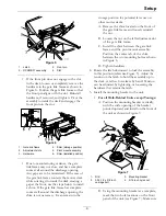
Страница 9: ...remain in the storage position for potential later use on other mower decks A Remove the shim located on the front of the gate link frame and loosely reinstall the nut B Loosen the nut on the left adjustment slot of the gate link frame C Install the shim between the gate link frame and the pivot mount assembly Position the center tab of the shim between the two mounting bolts as shown in Figure 6 ...

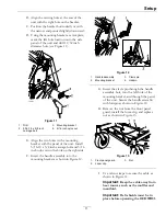
Страница 10: ...the front panel of the unit Install the hairpin through the hole on the clevis pin Figure 8 G If the mower deck is not equipped with belt shield knobs skip to step H If the deck does have belt shield knobs secure the loom clip by removing the rear knob on the belt shield Place the loom clip onto the belt shield stud and reinstall the knob onto the belt shield Figure 9 Figure 9 1 Knob 3 Handle asse...

Страница 11: ... nyloc nut in the hole on the right side F Insert the handle assembly into the mounting bracket as shown in Figure 12 Figure 12 1 Handle assembly 3 Clevis pin 2 Mounting bracket 4 Hairpin G Insert the clevis pin through the handle assembly hole into the left hole of the mounting bracket and through the panel of the unit Secure the handle assembly with hairpin as shown in Figure 12 H Remove the nut...

Страница 12: ...Product Overview Figure 14 1 Velcro strap 2 Loom clip Product Overview Figure 15 1 Handle 2 Discharge gate under discharge deflector 3 Discharge deflector 12 ...

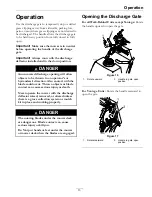
Страница 13: ...s direction Also contact with the blade could occur Thrown objects or blade contact can cause serious injury or death Never operate the mower with the discharge deflector raised removed or altered unless there is a grass collection system or mulch kit in place and working properly DANGER The rotating blades under the mower deck are dangerous Blade contact can cause serious injury or kill you Do No...

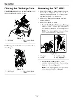
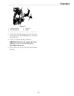
Страница 14: ... remove and retain the loom clip from the deck and replace the rear knob 2 Remove the hairpin and clevis pin from the handle assembly 3 Remove the handle assembly For all Walk Behind Units except Vantage Slide the handle assembly upward and out of the mounting bracket as shown in Figure 20 Note The mounting bracket does not have to be removed from the front panel Figure 20 1 Clevis pin 3 Handle as...

Страница 15: ...ssembly and pivot it away from the mower deck Lift the OCDWB01 out of the deck mounting tube 5 Lower the existing discharge deflector Important Reinstall the original discharge deflector if it was removed during the OCDWB01 installation 6 The machine can now be used for side discharge mowing 15 ...

Страница 16: ...nterval Before each use or daily 1 Stop engine wait for all moving parts to stop and remove key Engage parking brake 2 Visually inspect machine for any loose hardware or any other possible problem Tighten hardware or correct the problem before operating Check Discharge Gate Closure Service Interval Before each use or daily 1 Stop engine wait for all moving parts to stop and remove key Engage parki...

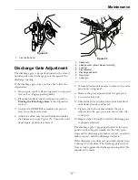
Страница 17: ...ge cover shown hidden for clarity 3 Lock nut 4 Pivot adjuster 5 Discharge deflector 6 Gate pivot 7 Cotter pin 5 If more adjustment is necessary remove the cotter pin shown in Figure 23 6 Remove the pivot adjuster from the gate pivot 7 Loosen the lock nut 8 Thread the pivot adjuster forward or backward until desired result is achieved 9 Tighten the lock nut and reinstall the pivot adjuster into the...

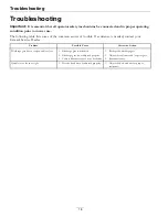
Страница 18: ...d contact your Exmark Service Dealer Problem Possible Cause Corrective Action 1 Discharge gate is deformed 1 Reshape the discharge gate 2 Discharge gate is not adjusted properly 2 Adjust the cable nuts and or pivot gate Discharge gate does not open and or close 3 Cable is disconnected at one or both ends 3 Reconnect cable Handle is too loose or tight 1 Pivot bolt and nut not adjusted properly 1 Ad...

Страница 19: ...y Company 2101 Ashland Avenue Beatrice NE 68310 402 223 6375 or service exmark com Owner s Responsibilities If your product requires warranty service it must be returned to an authorized Exmark service dealer within the warranty period This warranty extends only to commercial attachments and accessories operated under normal conditions You must read the operator s manual You must also properly ser...

Страница 20: ...N SYSTEM ULTRA VAC QUICK DISPOSAL SYSTEM OUT FRONT RIDING ACCESSORIES AND OPTIONS CUSTOM RIDE SEAT SUSPENSION SYSTEM DUAL TAIL WHEEL FLOOR PAN EXTENDER HITCH KIT LIGHT KIT MICRO MULCH SYSTEM ROLL OVER PROTECTION SYSTEM ROPS SNOW BLADE SNOWBLOWER SUN SHADE TRASH CONTAINER ULTRA VAC COLLECTION SYSTEM ULTRA VAC QUICK DISPOSAL SYSTEM WEATHER CAB Place Model No and Serial No Label Here Included in the ...

Отзывы: