background image

28 

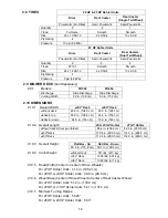
4.1.15 

Lubricate the brake rod bushings: 


Service Interval: 160 hrs.


a)  Stop engine, wait for all moving parts to stop, and remove key.  Engage 

parking brake.   

b)  Tilt seat forward and raise hood. 

c)  Lubricate bronze bushings on each end of the brake rod shaft with a spray 

type lubricant or light oil (bushings are located to the inside of the flange 
bearings). 

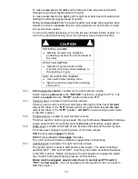
4.1.16 

Lubricate the motion control bronze bushings: 


Service Interval: 160 hrs.


a)  Stop engine, wait for all moving parts to stop, and remove key.  Engage 

parking brake.   

b)  Tilt seat forward. 

c)  Lubricate bronze bushings on the flange bearings securing the motion 

control arm shafts with a light oil or a spray type lubricant. 

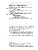
4.1.17 

Lubricate the motion control shaft: 


  Service 

Interval: 

Yearly. 

a)  Stop engine, wait for all moving parts to stop, and remove key.  Engage 

parking brake.   

b)  Tilt seat forward. 

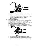
c)  Remove tab at rear of motion control shaft. 

d)  Pull motion control shaft out and lubricate with an NGLI grade #2 multi-

purpose gun grease. 

e)  Re-install shaft and tab. 

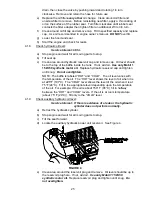
4.1.18 

Lubricate steering linkage rod ends: 


Service Interval: 160 hrs.


a)  Stop engine, wait for all moving parts to stop, and remove key.  Engage parking 

brake.   

b)  Tilt seat forward. 

c)  Lubricate each end of both steering linkage rods with a spray lubricant or light 

oil. 

4.1.19 

Remove engine shrouds and clean cooling fins: 


Service Interval: 80 hrs. 

a)  Stop engine, wait for all moving parts to stop, and remove key.  Engage 

parking brake.  

b)  Remove cooling shroud clean-out covers from engine and clean cooling fins.  

Also clean dust, dirt, and oil from external surfaces of engine, which can cause 
improper cooling. 

c)  Make sure cooling shroud clean-out covers are reinstalled.  Operating the 

engine without cooling shroud clean-out covers will cause engine damage due 
to overheating. 

4.1.20 

Check spark plugs: 


Service Interval: 160 hrs. 

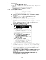
a)  Remove spark plugs, check condition and reset gaps, or replace with new 

plugs.  See Engine Owners Manual. 


Содержание Frontrunner FR20KC

Страница 1: ...For Serial Nos 600 000 Higher Part No 109 4288 Rev A ...

Страница 2: ...tory animals WHAT CAN HAPPEN Failure to use caution may cause serious injury or illness HOW TO AVOID THE HAZARD Avoid prolonged breathing of vapors Keep face away from nozzle and gas tank container opening Keep away from eyes and skin Never siphon by mouth IMPORTANT When the mower is used or operated on any California forest brush or grass covered land a working spark arrester must be attached to ...

Страница 3: ...bmitting the Exmark Parts Plus order to Exmark by 3 00 p m central time the Distributor pays for the part and freight 3 Exmark being unable to ship the part and the Exmark parts order is received by 3 00 p m central time Exmark pays for the part and freight 4 If the part does not arrive overnight due to the shipper UPS the shipper pays for the freight and Exmark pays for the part The following res...

Страница 4: ...maintain its maximum efficiency and promote safe operation If additional information is needed or should you require trained mechanic service contact your authorized Exmark equipment dealer or distributor All Exmark equipment dealers and distributors are kept informed of the latest methods of servicing and are equipped to provide prompt and efficient service in the field or at their service statio...

Страница 5: ... Hydrostatic Ground Drive System 13 2 8 Tires 14 2 9 Mower Deck 14 2 10 Dimensions 14 2 11 Torque Requirements 15 3 OPERATION INSTRUCTIONS 3 1 Controls 15 17 3 2 Pre Start 17 3 3 Operating Instructions 17 19 3 4 Transporting 19 20 4 MAINTENANCE ADJUSTMENTS 4 1 Periodic Maintenance 21 30 4 2 Adjustments 30 34 5 WASTE DISPOSAL 5 1 Motor Oil Disposal 35 5 2 Battery Disposal 35 6 TROUBLESHOOTING 35 36...

Страница 6: ...rd the Exmark mower as a piece of power equipment and teach this regard to all who operate this unit 1 2 2 Read the instructions carefully Familiarize yourself with the controls and the proper use of the equipment If the operator s or mechanic s can not read English it is the owner s responsibility to explain this material to them 1 2 3 Do not allow operation of this machine by untrained personnel...

Страница 7: ... trousers Do not operate equipment when barefoot or when wearing open sandals 1 3 4 Thoroughly inspect the area where the equipment is to be used and remove all stones sticks wires bones and other foreign objects which may damage the equipment or cause personal injury to the operator or bystanders WARNING POTENTIAL HAZARD Engine exhaust contains carbon monoxide which is an odorless deadly poison W...

Страница 8: ...ep it out of the reach of children Add fuel before starting the engine Never remove the cap of the fuel tank or add fuel when engine is running or when the engine is hot Never fill the fuel tank so that the gasoline level rises above a level that is 1 2 below the bottom of the filler neck to allow for gasoline expansion and prevent fuel spillage If fuel is spilled DO NOT attempt to start the engin...

Страница 9: ...ll gasoline containers inside a vehicle or on a truck or trailer bed because interior carpets or plastic truck bed liners may insulate the container and slow the loss of any static charge When practical remove gas powered equipment from the truck or trailer and refuel the equipment with its wheels on the ground If this is not possible then refuel such equipment on a truck or trailer from a portabl...

Страница 10: ... hazard control and accident prevention are partially dependent upon the design and configuration of the equipment these factors are also dependent upon the awareness concern prudence and proper training of the personnel involved in the operation transport maintenance and storage of the equipment It is essential that all Operator Safety Mechanisms be connected and in operating condition prior to u...

Страница 11: ... carry passengers DO NOT operate the mower when children or others are in the area 1 4 3 When feasible avoid operating the equipment in wet grass WARNING POTENTIAL HAZARD Operating a FrontRunner tractor without an approved Exmark front mount attachment increases the possibility of forward tip over WHAT CAN HAPPEN Tip over could cause serious injury or death HOW TO AVOID THE HAZARD When operating a...

Страница 12: ... Avoid sudden turns or rapid speed changes See inside the back cover to determine the approximate slope angle of the area to be mowed Use a walk behind mower and or a hand trimmer near drop offs ditches steep banks or water This area can be dangerous see Figure 1 FIGURE 1 Progressively greater care is needed as the slope increases Always avoid sudden starting or stopping on a slope If tires lose t...

Страница 13: ...ning or working on the mower After striking a foreign object inspect the mower for damage and make repairs before restarting and operating the mower Before clearing blockages Whenever you leave the mower Stop the engine and wait for all moving parts to stop Before refueling Before dumping the grass catcher 1 4 13 Before stopping the engine place the throttle control midway between the slow and fas...

Страница 14: ...1 5 4 Keep engine engine area and pump drive belt compartment free from accumulation of grass leaves excessive grease or oil and other debris which can accumulate in these areas These materials can become combustible and may result in a fire 1 5 5 Store fuel in a container specifically designed for this purpose in a cool dry place 1 5 6 Keep the mower and fuel container in locked storage to preven...

Страница 15: ...y relieve all pressure in the hydraulic system by placing the motion control levers in neutral and shutting off the engine before performing any work on the hydraulic system 1 6 SAFETY SIGNS 1 6 1 Keep all safety signs legible Remove all grease dirt and debris from safety signs and instructional labels 1 6 2 Safety signs must be replaced if they are missing or illegible 1 6 3 When new components a...

Страница 16: ... NO 107 2102 LOCATION Inside Surface of Upper Roll bar PART NO 107 2112 LOCATION Top of Floor Pan PART NO 109 2355 LOCATION Outside of each Bell Crank PART NO 109 2358 LOCATION On Control Panel PART NO 109 2357 LOCATION Top of Console LH Side PART NO 109 2356 LOCATION Top of Console RH Side PART NO 109 2360 LOCATION Front of Console PART NO 109 2377 LOCATION On Hydraulic Cylinder PART NO 109 2396 ...

Страница 17: ...on Kohler P N 2405010 2 3 4 Fuel Shut Off Valve 1 4 turn in line valve by fuel filter 2 4 ELECTRICAL SYSTEM 2 4 1 Charging System Flywheel Alternator 2 4 2 Charging Capacity 15 amps 2 4 3 Battery Type BCI Group U1 2 4 4 Battery Voltage 12 Volt 2 4 5 Polarity Negative Ground PART NO 109 2699 LOCATION On Control Panel PART NO 109 3637 LOCATION Back of Seat PART NO 93 4361 LOCATION On LH and RH Side ...

Страница 18: ...inged to tilt up for access to hydraulic pumps battery and other components The seat is held in the tilted position with a linkage Adjustable fore and aft seat track 2 6 3 Seat Safety Switch Internal to the bottom seat cushion non serviceable Time delay module incorporated into the Safety Interlock System eliminates rough ground cut outs 2 6 4 Armrests Standard seat foam padded flip up armrests Op...

Страница 19: ...ck 49 0 in 124 5 cm 49 0 in 124 cm deflector up 53 3 in 135 4 cm 61 4 in 156 cm deflector down 64 0 in 163 cm 72 0 in 183 cm 2 10 2 Overall Length 20 23 HP Kohler 27 HP Kohler without deck floor pan folded 80 4 in 204 2 cm 82 3 in 209 0 cm w 52 Deck 112 4 in 285 5 cm 114 3 in 290 3 cm w 60 Deck 112 4 in 285 5 cm 114 3 in 290 3 cm 2 10 3 Overall Height Roll Bar Up Roll Bar Down 69 2 in 175 8 cm 50 ...

Страница 20: ... the left drive wheel motor The right lever controls the flow of hydraulic oil from the right hydrostatic pump to the right drive wheel motor IMPORTANT To begin movement forward or backward the operator must be in the seat the brake lever must be disengaged pushed down before the motion control levers can be moved in or the engine will kill When levers are centered in the T slot the drive system i...

Страница 21: ... 4 Choke Control Located on right fuel tank console Choke is used to aid in starting a cold engine Moving the choke lever forward will put the choke in the ON position and moving the choke lever to the rear will put the choke in the OFF position DO NOT run a warm engine with choke in the ON position 3 1 5 Throttle Control Located on right fuel tank console Throttle is used to control engine speed ...

Страница 22: ...e to be pushed without the engine running With a wrench turn both valves one turn counter clockwise to release drive system Turn clockwise to reset system DO NOT overtighten DO NOT tow machine For 27 HP Kohler Units Use a 5 8 wrench to turn the valves For 20 HP 23 HP Kohler Units Use a 7 16 wrench to turn the valves 3 2 PRE START 3 2 1 Fill fuel tank For best results use only clean fresh regular g...

Страница 23: ...dually return choke to the OFF position as the engine warms up On a warm engine place the throttle midway between the SLOW and FAST positions and leave the choke in the OFF position 3 3 4 Engaging PTO DANGER POTENTIAL HAZARD The rotating blades under the mower deck are dangerous WHAT CAN HAPPEN Blade contact can cause serious injury or kill you HOW TO AVOID THE HAZARD DO NOT put hands or feet unde...

Страница 24: ...chine will not be used for a few days when transporting and when the unit is parked inside a building 3 4 TRANSPORTING IMPORTANT Do not transport FrontRunner tractor without an approved Exmark front mount attachment 3 4 1 Transporting a Unit Use a heavy duty trailer or truck to transport the machine Engage the park brake and block the wheels Securely fasten the machine to the trailer or truck with...

Страница 25: ...oading units on trailers or trucks One full width ramp is required If it is not possible to use one full width ramp use enough individual ramps to simulate a full width continuous ramp Ramp should be long enough so that the angles between the ramp and the ground and the ramp and the trailer or truck do not exceed 15 A steeper angle may cause mower deck components to get caught as the unit moves fr...

Страница 26: ...engine to cool completely before service or making repairs around the engine area 4 1 PERIODIC MAINTENANCE 4 1 1 Check engine oil level Service Interval Daily a Stop engine and wait for all moving parts to stop Make sure unit is on a level surface b Tilt seat forward and raise hood to gain access to access to engine area c Check with engine cold d Clean area around dipstick Remove dipstick and wip...

Страница 27: ...ss to avoid damaging the battery see chart below for recommended charger settings Voltage Reading Percent Charge Maximum Charger Settings Charging Interval 12 6 or greater 100 16 volts 7 amps No Charging Required 12 4 12 6 75 100 16 volts 7 amps 30 Minutes 12 2 12 4 50 75 16 volts 7 amps 1 Hour 12 0 12 2 25 50 14 4 volts 4 amps 2 Hours 11 7 12 0 0 25 14 4 volts 4 amps 3 Hours 11 7 or less 0 14 4 v...

Страница 28: ...ngage parking brake and raise off of seat but do not get off of machine engine must stop after approx 1 2 second has elapsed seat has time delay kill switch to prevent cut outs on rough terrain Run engine at one third throttle engage PTO and raise off of seat but do not get off of machine engine must stop after 1 2 second has elapsed Run engine at one third throttle with brake disengaged move leve...

Страница 29: ...nner element Replace whenever it appears dirty typically every other time the paper element is replaced Clean the base around the inner element before removing so dirt does not get into the engine f DO NOT wash or use pressurized air to clean paper element or inner element g Reinstall elements Position the cover so that the rubber dust ejector is pointing downward and secure with retaining clips F...

Страница 30: ...l 1 15W 50 synthetic motor oil Replace hydraulic reservoir cap and tighten until snug Do not overtighten NOTE The baffle is labeled HOT and COLD The oil level varies with the temperature of the oil The HOT level shows the level of oil when it is at 225 F 107 C The COLD level shows the level of the oil when it is at 75 F 24 C Fill to the appropriate level depending upon the temperature of the oil F...

Страница 31: ...ection 4 2 2 and 4 2 3 for belt replacement 4 1 12 Lubricate grease fittings Service Interval Refer to chart a Stop engine wait for all moving parts to stop and remove key Engage parking brake b Lubricate fittings with one to two pumps of NGLI grade 2 multi purpose gun grease Refer to the following chart for fitting locations and lubrication schedule LUBRICATION CHART Fitting Locations Initial Pum...

Страница 32: ...de the nut i Insert the assembled nut and axle into the wheel on the side of the wheel with the new seal and bearing j With the open end of the wheel facing up fill the area inside the wheel around the axle full of NGLI grade 1 multi purpose grease k Insert the second bearing and new seal into the wheel l Apply a thread locking adhesive to the 2 nd spacer nut and thread onto the axle with the wren...

Страница 33: ...ar of motion control shaft d Pull motion control shaft out and lubricate with an NGLI grade 2 multi purpose gun grease e Re install shaft and tab 4 1 18 Lubricate steering linkage rod ends Service Interval 160 hrs a Stop engine wait for all moving parts to stop and remove key Engage parking brake b Tilt seat forward c Lubricate each end of both steering linkage rods with a spray lubricant or light...

Страница 34: ...r as stated in Section 4 1 8 CAUTION POTENTIAL HAZARD Raising the mower deck for service or maintenance relying solely on mechanical or hydraulic jacks could be dangerous WHAT CAN HAPPEN The mechanical or hydraulic jacks may not be enough support or may malfunction allowing the unit to fall which could cause injury HOW TO AVOID THE HAZARD DO NOT rely solely on mechanical or hydraulic jacks for sup...

Страница 35: ...acer nuts f Fuel tank bulkhead fitting nuts g Motion control tab retaining bolt 4 1 26 Dielectric grease is used on blade type electrical connections to prevent corrosion and loss of contact 4 2 ADJUSTMENTS IMPORTANT Disengage PTO shut off engine wait for all moving parts to stop engage parking brake and remove key before servicing cleaning or making any adjustments to the unit 4 2 1 Pump Drive Be...

Страница 36: ...the lower end of the linkage rod See Figure 8 FIGURE 8 f If the linkage does not measure 7 3 8 18 7 cm or still does not disengage as desired remove the bolt that secures the ball joint to the brake lever and loosen the jam nut next to the ball joint Rotate the ball joint in half turns counter clockwise until desired disengagement is obtained 4 2 4 Adjust Throttle Lever Tension a Stop engine wait ...

Страница 37: ...t neutral a Remove the electrical connection from the seat safety switch located directly in front of the seat switch assembly b The neutral adjustment must be made with the drive wheels turning Raise the frame and place on jack stands so that drive wheels can rotate freely Temporarily install a jumper wire across the terminals in the connector of the wiring harness c Start the engine d Run the un...

Страница 38: ...nt of weight onto the drive wheels This setting provides the greatest amount of traction Some conditions may require the rear wheel lift to be reduced This can be done by reducing the amount to weight transfer which will increase the amount of weight on the front and rear castors a Rotate the left motion control arm up and into the operation position b Locate and loosen the knob under the rear of ...

Страница 39: ...ight transfer spring that retains it to the transfer bellcrank pins and or weight transfer spring anchor pins See Figure 12 f Pull the spring off of front or rear pin and re install in the outer hole to reduce the spring force Re install the washer and retaining ring FIGURE 12 g Re install the left fender h For additional weight transfer adjustment repeat steps steps d through g on the right side ...

Страница 40: ...le return the battery to any certified battery reseller 6 TROUBLE SHOOTING 6 1 MOWER PULLS LEFT OR RIGHT WITH LEVERS FULLY FORWARD a Refer to Tracking Adjustment Section 4 2 5 b Check air pressure in drive tires For 20 and 23 HP Kohler Units The drive tires should be inflated to 13 psi 90 kpa For 27 HP Koher Units The drive tires should be inflated to 9 psi 62 kpa For All Units Semi pneumatic cast...

Страница 41: ...res to separate the connectors NOTE After carefully checking the above steps attempt to start the engine If it does not start contact your authorized Exmark service dealer IMPORTANT It is essential that all operator safety mechanisms be connected and in proper operating condition prior to mower use When a problem occurs do not overlook the simple causes For example starting problems could be cause...

Страница 42: ...37 7 ELECTRICAL DIAGRAM ...

Страница 43: ...38 8 HYDRAULIC DIAGRAM ...

Страница 44: ...sfied with the Service Dealer s analysis or with the assistance provided contact us at Exmark Customer Service Department The Exmark Warranty Company 2101 Ashland Avenue Beatrice NE 68310 402 223 6375 or service exmark com Owner s Responsibilities The Exmark turf equipment including any defective part must be returned to an authorized Exmark service dealer within the warranty period This warranty ...

Страница 45: ... as required maintenance in the written instructions must be warranted for the warranty period of two years If any such part fails during the period of warranty coverage it must be repaired or replaced by Exmark Manufacturing Company Any such part repaired or replaced under the warranty must be warranted for a time not less than the remaining warranty period B Any warranted part that is scheduled ...

Страница 46: ...41 NOTES ...

Страница 47: ...42 ...

Страница 48: ...AC QUICK DISPOSAL SYSTEM WALK BEHIND ACCESSORIES GRASS CATCHER MICRO MULCH SYSTEM STEERABLE SULKY SULKY HITCH KIT TURF STRIPER STANDON WARNING The engine exhaust from this product contains chemicals known to the State of California to cause cancer birth defects or other reproductive harm 2005 2006 PART NO 109 4288 Rev A EXMARK MFG CO INC 402 223 6300 INDUSTRIAL PARK BOX 808 FAX 402 223 5489 BEATRI...

Отзывы: