Introduction
4
QA-805 and W2CM Interface Module
Physical Description of QA-805 Unit
Physical Description of QA-805 Unit
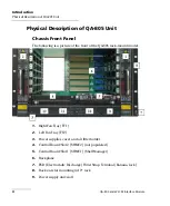
Chassis Front Panel
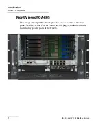
The following is a picture of the front of the QA-805 rack-mount model.
1.
Right Fan Tray [FT1]
2.
Left Fan Tray [FT2]
3.
Power supplies cover and air filter holder
4.
Control Board/Slot 2 [SHMC2] (not populated)
5.
Control Board/Slot 1 [SHMC1] (Shelf Manager)
6.
Backplane
7.
ESD (Electrostatic Discharge) Wrist Strap Terminal (Banana Jack)
8.
Rack ears for mounting in 19” rack
9.
Power supply unit/slot 1
Содержание Quality Assurer QA-604
Страница 1: ...User Guide QA 805 and W2 CM Interface Module...
Страница 8: ......
Страница 30: ......
Страница 44: ......
Страница 52: ......


