CM-ECCS-U441TB
Page 6 of 7
[email protected] www.excelwavetechnologies.com 1-888-329-2878(Tel) 1-888-318-5528(Fax) Rev.2
©All rights reserved, 2018
4.
Frequency band shift
. Gently move up and down the tuning rods with the screw driver to shift
the band to desired new band then lock the nuts. Move the frequency tuning rods clockwise will
lower the frequency, move the frequency tuning rods counter clockwise will increase the
frequency. Move up and down the tuning rods smoothly and switch between each rod to maintain
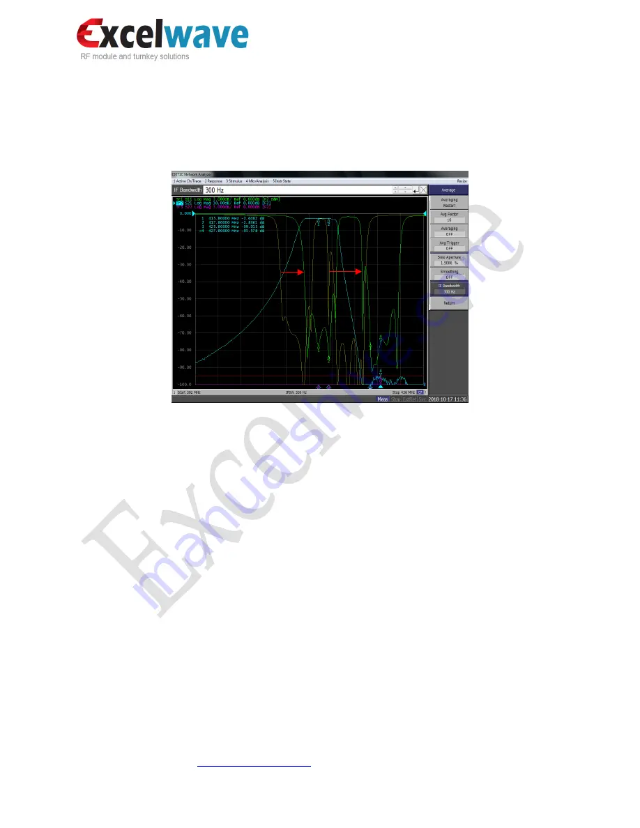
the shape of the VNA plots, as the example shown in Fig,7.
Fig.7 An example of 5MHz frequency shift by tuning
Yellow-The original frequency band
Green-The retuned frequency band
5.
Bandwidth adjustment
. The bandwidth is pre-set at factory and not tunable except minor
adjustable to compensate the effect of frequency band shift. Move the bandwidth tuning rods
clockwise will widen the bandwidth, while counter clockwise will narrow the bandwidth.
6.
VSWR optimization
. The tuning in step-2 and step-3 may affect the VSWR, which can be
compensated by the combined tuning between each rod. During the tuning process, if moving
down a tuning rod will increase the VSWR, then move up the tuning rod to improve the VSWR
and try to move other rods to achieve the attempted frequency shift or bandwidth adjustment.
7.
Rejection.
The Tx-Rx rejection is pre-set at factory and usually does not need tuning. In case it is
needed, tuning rods T1 or R1 can be used to optimize the rejection.
8.
Verification.
Inspect all the parameters and ensure all meet the specification. Ensure each tuning
rod screw is tightened and the performance is stable when pushing the tuning rods. Replace the
cover and lock it by the screws.


