S
O
U
N
D
E
R
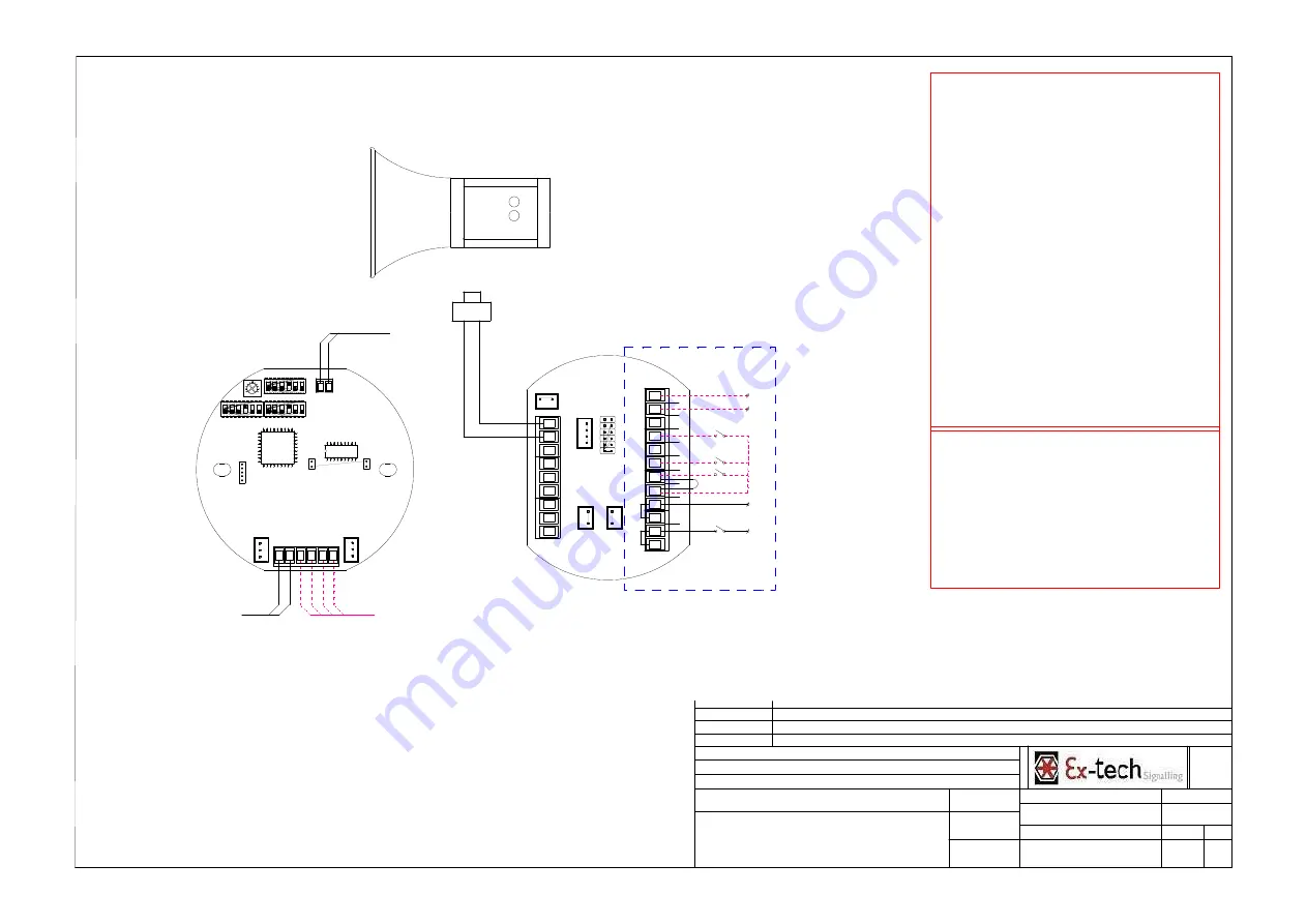
Wiring For Customer
L
N
Tel
Tel
TB-SD
CN-S/D
Tel Line
Part NO.:50TBSSAD100
S0
L
N
S1
S2
S0
S1
S2
N("0" )
L("B+" )
SW-A
SW-B
TO CN-S/D
TO
TB-SD
CN-SP
Dly
Dly
SP-
SP+
SW-Dly
SOUNDER
1
2
3
4
5
6
ON
DIP
1
2
3
4
5
6
ON
DIP
1
2
3
4
5
6
ON
DIP
SOUNDER PCB
SPEAKER
S1 S2
S0
N
L
Dly
TO CN-SP
Wiring Method
Factory default settings
1. S0 and S1 are connected (default stage 1 alarm output).
2. Connect power supply line to terminals "L" and "N". If
power supply is DC. "L" presents "+". "N" presents "0".
3. The unit will alarm (default stage 1 alarm output) when
power is on.
Three stages alarm output settings
1. Connect power supply line to terminals "L" and "N". If
power supply is DC. "L" represents "+". "N" represents "0".
2. Connect S1 to S0 for stage 1 alarm output
Connect S2 to S0 for stage 2 alarm output
Connect S1\S2 to S0 for stage 3 alarm output
3. The unit won't alarm when power is on.
4. The unit will alarm as stage 1 when switch 1 is on.
The unit will alarm as stage 2 when switch 2 is on.
The unit will alarm as stage 3 when switches 1/2 are on.
Telephone Initiated PCB Function
1. Connect the telephone line to the "Tel" terminals.
2. The unit will alarm when telephone rings.
3. The unit will stop alarming when the telephone handset is
picked up.
Please refer to our product technical manual for more details.
Cable Selection
Please select suitable size cable according to the distance
between control room & the terminals and the quantity of
equipments used.
Normal size for AC power supply cable L & N is 1.5mm². Normal
size for DC power supply cable L & N is 2.5mm².
Please select the quantity of control cables (0 to 4)according to
the actual requirement. Normal size for control cable is 1mm².
01
WIRING DIAGRAM SD100_125_150
-
-
P. TRAUMAT
15/02/2016
Drawing part
1 : 1
1/1
Specifications
Treatment
Material
N° Drawing
Scale :
Drawn by :
Date :
A3
Size :
Dossier
Folio
Index
Revision - date
00 - 15/02/2016
Reason
Création
SD100_125_150
Project / N° PO


