Design and function
Remote control
099-005542-EW501
24.03.2020
55
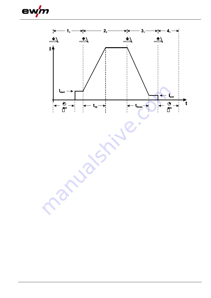
Latched mode
Figure 5-44
1st cycle
• Press and hold torch trigger.
• Shielding gas is expelled (gas pre-flows).
The arc is ignited using liftarc.
• The welding current flows with the value set for the starting current I
start
.
2nd cycle
• Release torch trigger.
• Welding current increases to the main current in the set upslope time.
3rd cycle
• Press and hold torch trigger.
• The main current falls in the set downslope time to the end-crater current I
end
.
4th cycle
• Release torch trigger, arc is extinguished.
• Gas post-flow time elapses.
The welding process is terminated immediately if the torch trigger is released during the
downslope time.
The welding current drops to zero and the gas post-flow time begins.
5.5 Remote control
The remote controls are operated on the 19-pole remote control connection socket (analogue).
5.6 Special parameters (advanced settings)
Special parameters (P1 to Pn) are applied for customer-specific configuration of machine functions. This
allows the user maximum flexibility in optimising their requirements.
These settings are not configured directly on the machine control since a regular setting of the parame-
ters is generally not required. The number of selectable special parameters can deviate between the ma-
chine controls used in the welding system (also see the relevant standard operating instructions).
If required, the special parameters can be reset to the factory settings
> see 7.4 chapter
.


