Design and function
Degaussing
26
099-002129-EW501
15.10.2020
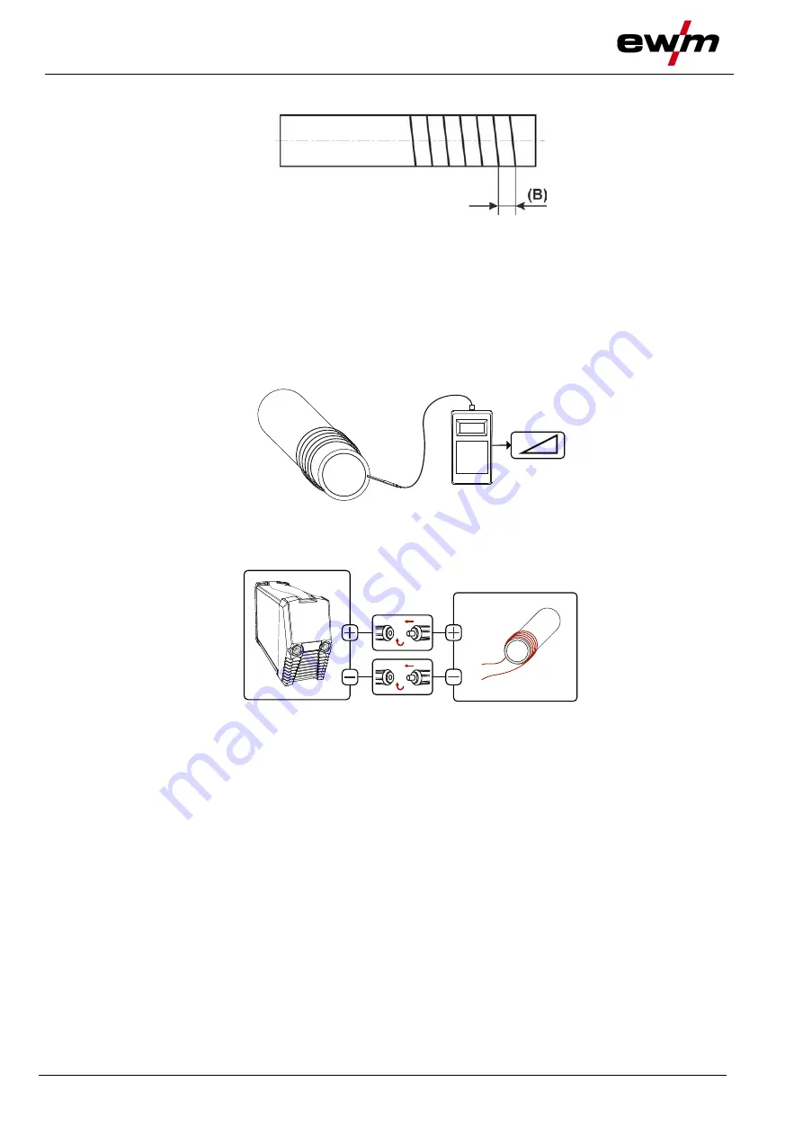
Large or long workpieces
Figure 5-22
• Lay power cables tightly around the component.
• Lay power cables up to the welding-relevant area, such as the sidewall of the joint.
If the space required by the power lines is too large, the turns can also be placed on top of each
other. This has no significant influence on the degaussing process.
As the distance between the individual turns (B) increases, the current must be corrected
upwards to achieve the desired result.
5.6.3 Generating an opposing magnetic field during welding (activgauss)
Figure 5-23
• Measure the magnetic flux density.
Figure 5-24
• Lay power cables tightly around component
> see 5.6.2 chapter
.
• Connect power cables to the power source (the polarity is freely selectable).


