


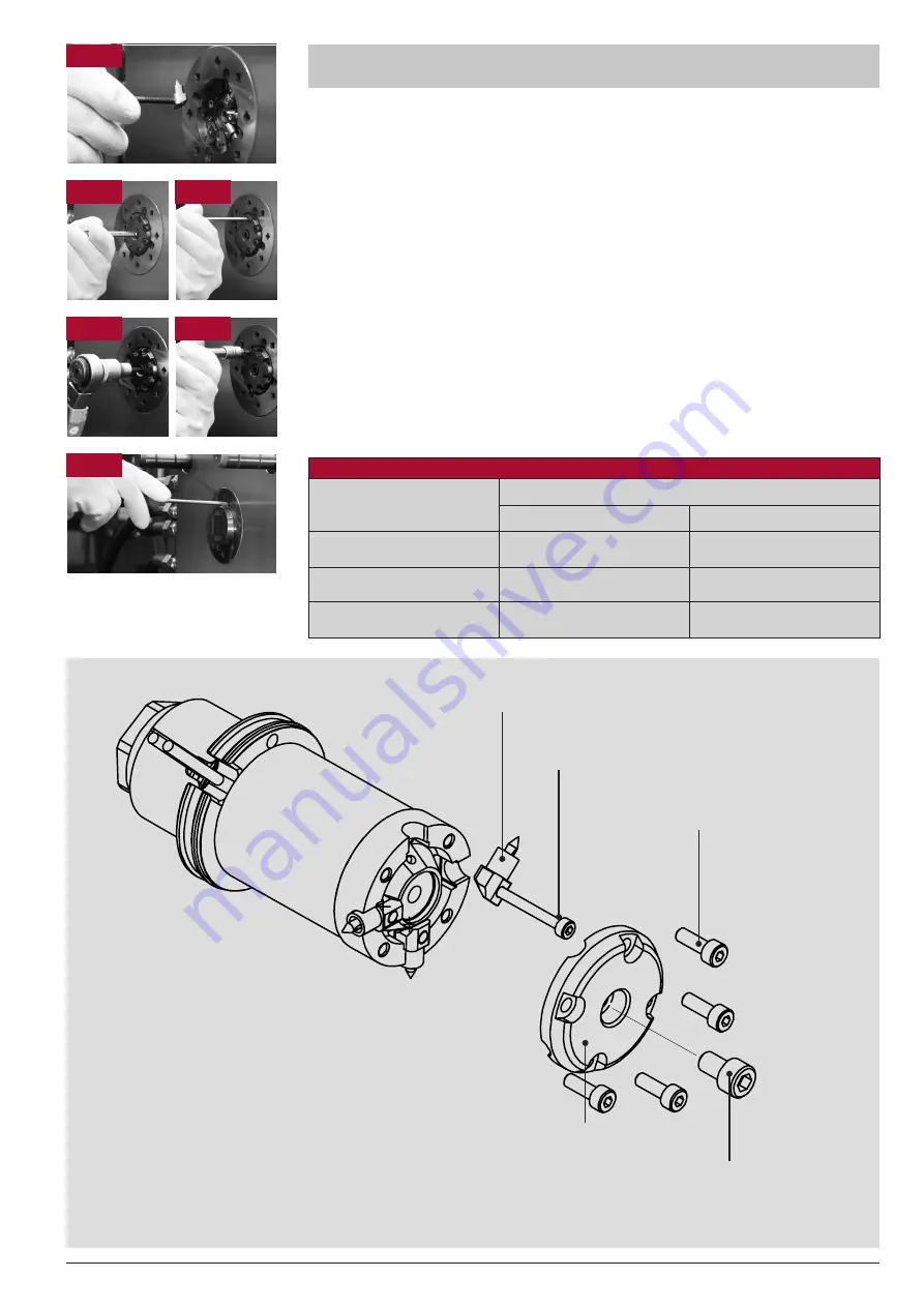
Tip insert assembly for the
HPS III-MHR nozzle, radial version
1x socket head screw
ISO 4762 M6x10
1. Install the tip inserts. Please ensure that they are positioned correctly and that the sealing
surfaces between tip insert and nozzle are clean. A screw M4 or a threaded rod can be
screwed into the tip insert as an assembly aid.
2. Attach clamping cover and fix it with central socket head screw M6x10.
Use half of the defined torque (please see chart).
3. Screw in socket head screws M4x12 crosswise. Use half of the defined torque
(please see chart).
4. Heat up nozzle to processing temperature (maximum nozzle temperature 350 °C / 662 °F)
and warm up the mould until the mould temperature is reached. Keep the resulting ΔT
(difference between processing and mould temperature) for at least 10 minutes before
finally retightening the screws with the matching torque. Not adhering to this procedure can
result in damaged sealing sleeves and leakage.
5. Retighten central socket head screw M6x10 with defined torque (see table).
6. Retighten socket head screws M4x12 crosswise with defined torque (see table).
7. Install heat protective cover.
Page 3/4
Tip insert
Assembly aid (socket head screw M4)
4x socket head screw
ISO 4762 M4x12-12.9
1x socket head screw
ISO 4762 M6x10-12.9
Clamping cover
The number of
the M4x12 socket
head screws varies
depending on
the number of
tip inserts.
1
5
6
7
2
3
Versions of
HPS III-MHR
radial nozzle
Nozzle
Torque (unlubricated)
M4x12 - 12.9
M6x10 - 12.9
MHR 93/95 /
MHR100 / MHR111
4 Nm (3.0 ft·lb)
11 Nm (8.1 ft·lb)
MHR112 / MHR122
2.5 Nm (1.8 ft·lb)
Central socket head screw not
available for this version
MHR200
4 Nm (3.0 ft·lb)
2 tips: 6 (4.4 ft·lb)
4 tips: 11 (8.1 ft·lb)