EWC Controls Inc. 385 Highway 33 Englishtown, NJ 07726 800-446-3110 FAX 732-446-5362 E-Mail- [email protected]
2
BYPASS SIZING CALCULATIONS
BYPASS SIZING CALCULATIONS
The bypass damper must be installed horizontal & level between the supply duct and the return duct.
Position the damper to open in the direction of airflow back to the return duct or into a conditioned area.
Place the duct connection on the return so that the bypass air has a minimum 6 feet of return duct. before it
enters the air handler, if space permits.
If a Restricting Hand Damper is installed, it should have been setup
already. If not, refer to Application note 090376A0169D. Otherwise, close the hand damper ½ way.
Position the ARM in the “IDEAL ARM LOCATION” for the correct direction of air flow and tighten the
thumb screw. (Refer to page 4)
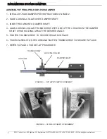
Position the
Extra Weight (optional)
high up on the ARM and tighten the thumb screw. Position
Weight#1
towards the bottom of the arm and tighten the thumb screw. (Refer to page 3)
Energize
ALL
Zones to operate the unit with the Fan running on the Highest speed. (Usually a Cooling
demand, 2nd stage if applicable)
Return to the damper & confirm that the by-pass damper is closed. If necessary, reposition the
Extra Weight
or Weight #1
lower on the ARM until the damper closes completely. (It should be closed to the point where
any additional force will start to open it) (Refer to page 3)
Turn off all Zones but the Smallest Zone & Wait about 45 seconds.
Monitor the airflow for the Smallest Zone.
Is there to much Airflow or Noise? Proceed to
Step 9
.
Is there Insufficient Airflow? Proceed to
Step 10
.
Is the Airflow Acceptable? Proceed to
Step 11
.
Excess Velocity:
Reposition the
Extra Weight
higher up on the ARM until the velocity in the smallest zone
has subsided to an acceptable level. If the velocity remains high, reposition
Weight #1
higher up on the arm,
or if necessary, reposition the ARM closer towards “6 or 0” on the scale.
(Depending on the model).
Insufficient Velocity:
Reposition the
Extra Weight
lower on the ARM until the velocity is at an acceptable
level. If the velocity remains low, reposition the ARM closer towards the “3 or 9” on the scale (
(Depends on
model. Refer to page 3&4)
depending on direction of flow). If velocity still remains low for the smallest zone, to
much air is being forced through the barometric damper. You can order additional weights or you should
consider installing an Electronic By-Pass Damper (Model EBD).
Congratulations, your PRD By-Pass damper is now properly adjusted.
1.
2.
3.
4.
5.
6.
7.
8.
9.
10.
11.
BAROMETRIC BYPASS SET-UP PROCEDURE
BAROMETRIC BYPASS SET-UP PROCEDURE
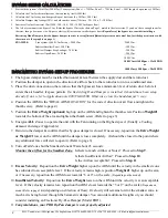
Start with the system’s Total Cfm (2000Cfm) 3 zone system (Zone 1 = 750Cfm, Zone 2 = 750Cfm, Zone 3 = 500Cfm plus 4 open runs @ 50Cfm)
Calculate the Cfm for the smallest zone that can run by itself (500Cfm)
Calculate the Cfm for any non-dampered (open) duct runs (4 x 50Cfm = 200 Cfm)
Calculate Damper stop leakage (20%) on both inactive zones (750cfm x .20 = 150 x 2 = 300Cfm)
Subtract all values from total Cfm (2000 - 500 - 300 - 200 = 1000 Cfm bypass flow)
The left over amount is the bypass Cfm. Refer the bypass Cfm to the chart on Page 1, match to the closest size. If you don’t have enough room for
that size, then go down one size. By-pass velocity will increase on smaller bypass ducts.
Regardless of the bypass size, consider installing a
Restricting Hand Damper after the Bypass damper, in order to set sufficient differential pressure and control how fast the bypass air mixes with
the return air. (See graphic on page 1)
EXAMPLE:
5 ton system @ 400 Cfm Per ton = 2000 Cfm
2000 Cfm
Subtract Smallest Zone = 500 Cfm
-500 Cfm
Subtract Damper Stop Leakage = 300 Cfm
-300 Cfm
Subtract Open Runs = 200 Cfm
-200 Cfm
1000 Cfm
1000 Cfm @1400Fpm = 12x10 PRD
or
1000 Cfm @ 900 Fpm = 20x10 PRD
1.
2.
3.
4.
5.
6.


