Evolution R255MTS Скачать руководство пользователя страница 17

17

www.evolutionpowertools.com

EN

•  Gently move the fence rail to the right or left until the ‘0’ 

position on the scale coincides with the datum line in the 
magnifier. 

(Fig. 13)

•  Check, and when satisfied that calibration has been 

achieved, tighten the seven fence rail nuts 

(S)

 securely.

•  Lower the blade.

Note: 

The rip fence simply slots into the fence rail, and can be 

locked into position anywhere along the rails length, and at either 
side of the machine by pressing the locking lever downwards.

CHECKING/ADJUSTING THE RIP FENCE

When the fence rail and rip fence have been attached to the 
machine, the rip fence should be checked to ensure that it lies 
parallel to the blade.

•  Raise the blade to its full height.
•  Rest a straight-edge or similar against the blade.
•  Bring the rip fence up to the straight-edge and check  

for parallelism.

•  If adjustment is needed, gain access to the two socket 

headed screws through the two holes in the carrier. 

(Fig. 14)

•  Loosen these screws using the correct sized hex key,  

and adjust the fence as required.

•  Tighten and re-check the rip fence when correct alignment 

has been achieved.

•  Lower the blade.

SLIDING MITRE GAUGE

Note: 

The sliding mitre gauge 

(K)

 fits in either of the inverted 

‘T’ slots in the machine table.

The adjustable aluminium faceplate is held in the protractor base 
of the mitre gauge by two machine screws and thumb nuts. 

The anti-bounce device 

(I)

 can be fitted into the socket 

incorporated into the mitre gauge base. 

(Fig. 15) 

Turning the 

locking handle anti-clockwise 

(Fig. 16)

 allows the mitre gauge 

angle to be adjusted.  Use the protractor scale and pointer and 
set the gauge to the desired angle. Tighten the vertical handle 
when the required angle has been selected.

Note: 

It is recommended that the anti-bounce device is fitted 

only when needed (e.g. when cutting thin sheet material or 
thin walled metal tube etc). At other times safely store the 
device off the machine.
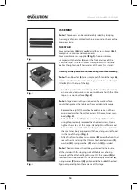
Fig. 13

Fig. 15

Fig. 14

Fig. 16

Содержание R255MTS

Страница 1: ...Original written in UK English Date Published 11 06 2018 Original Instructions MTS ...

Страница 2: ...e 14 Attaching the Table Extensions Page 15 The Fence Rail Page 16 Adjustment Page 16 Checking Adjusting the Rip Fence Page 17 Sliding Mitre Gauge Page 17 Top Blade Guard Page 18 OPERATION Page 19 On Off Safety Switch Page 19 Raising Lowering the Blade Page 19 Tilting the Blade Page 20 Rip Fence Guide Page 21 Dual Read Scale Page 21 Mitre Gauge Page 21 Anti Bounce Device Page 22 Basic Table Saw Op...

Страница 3: ...wide organization but technical help is also available from your supplier WEB www evolutionpowertools com EMAIL customer services evolutionpowertools com WARRANTY 1 4 Congratulations on your purchase of an Evolution Power Tools Machine Please complete your product registration online as explained on the leaflet included with this machine This will enable you to validate your machine s warranty per...

Страница 4: ...ness 1 8mm 5 64 No Load Speed 3250min 1 3250rpm Weight 20 25kg 44 7lbs CUTTING CAPACITY METRIC IMPERIAL Maximum depth of cut at 90 85mm 3 1 4 Maximum depth of cut at 45 65mm 2 1 2 Mild Steel Plate Optimal Cutting Thickness 3mm 1 8 Mild Steel Box Section Opt Wall Thickness 3mm 1 8 Rip Capacity Right Of The Blade 410mm 16 1 8 In BLADE METRIC IMPERIAL Diameter 255mm 10 Bore 25 4mm 1 Kerf 2mm 1 8 ...

Страница 5: ...ible appropriate working practices adopted Managing these factors can help reduce the effects of vibration Handling Handle the machine with care allowing the machine to do the work Avoid using excessive physical effort on any of the machines controls Consider your security and stability and the orientation of the machine during use Work Surface Consider the work surface material its condition dens...

Страница 6: ... with an appropriate blade this machine can be used to cut Mild Steel Max Thickness 3mm Aluminium Max Thickness 3mm Wood and wood based materials Max Thickness 85mm 1 11 PROHIBITED USE OF THIS POWER TOOL WARNING This product is a table saw and must only be used as such It must not be modified in any way or used to power any other equipment or drive any other accessories other than those mentioned ...

Страница 7: ... battery operated cordless power tool 2 2 1 General Power Tool Safety Warnings Work area safety a Keep work area clean and well lit Cluttered or dark areas invite accidents b Do not operate power tools in explosive atmospheres such as in the presence of flammable liquids gasses or dust Power tools create sparks which may ignite the dust or fumes c Keep children and bystanders away while operating ...

Страница 8: ...at these are connected and properly used Use of dust collection can reduce dust related hazards 2 5 4 General Power Tool Safety Warnings Power tool use and care a Do not force the power tool Use the correct power tool for your application The correct power tool will do the job better and safer at a rate for which it was designed b Do not use the power tool if the switch does not turn it on or off ...

Страница 9: ... objects being thrown towards your eyes which could result in severe eye damage Before beginning power tool operation always wear safety goggles or safety glasses with side shield or a full face shield where necessary ADDITIONAL SAFETY INSTRUCTIONS TABLE SAWS WARNING Before using your table saw it is important that you read and understand these safety rules Failure to follow these rules could resu...

Страница 10: ...ke sure any extension cord is in good condition When using an extension cord be sure to use one heavy enough to carry the current your machine will draw An undersized cord will cause a drop in line voltage resulting in loss of power and possible overheating Always use safety glasses Also use a face or dust mask if the cutting operation is dusty Everyday eyeglasses only have impact resistant lenses...

Страница 11: ...eriod Dispose of the packaging in an environmentally responsible manner Recycle if possible Do not let children play with empty plastic bags due to the risk of suffocation 4 2 ITEMS SUPPLIED Description Quantity Instruction Manual 1 Multi Material TCT Blade 1 Table Extensions 2 Table Extension Support Struts 4 Leg Set 4 corner Legs 1 Set Cross Braces 4 Rubber Feet 4 Blade Guard with Extraction Por...

Страница 12: ... 1 4 1 ON OFF SWITCH 2 RIVING KNIFE 3 BLADE GUARD 4 BLADE 5 BEVEL LOCKING KNOB 6 RISE AND FALL BEVEL ADJUSTMENT HAND WHEEL 7 RIP FENCE SCALE MAGNIFIER 8 RIP FENCE LOCKING HANDLE 9 PUSH STICK 10 RIP FENCE 11 REAR CANTILEVER BRACES 12 ANTI BOUNCE DEVICE 13 SLIDING MITRE FENCE ...

Страница 13: ... 4 F SIDE TABLE EXTENSION PANELS x 2 G SIDE TABLE SUPPORT STRUTS x 4 H BLADE GUARD x 1 I ANTI BOUNCE DEVICE x 1 J RIP FENCE x 1 K MITRE GAUGE x 1 L FENCE RAIL 2 pieces M FENCE RAIL JOINING TONGUE x 1 N HEX HEADED SCREW x 28 O WASHER x 28 P SPRING WASHER x 28 Q NUT SILVER x 28 R COACH BOLT BLACK x 7 S NUT BLACK x 7 WHAT S IN THE BOX H I J N O P Q R S A E B C D K F G M L ...

Страница 14: ...e clean cloth positioned on the work surface would help protect the table top from accidental damage Remove the eight Ø10 mm hex headed screws and their associated washers from the corners of the machines main body Fig 3 Attach the four legs A to the main body of the machine using the previously removed hex headed screws Do not tighten the screws at this stage Hand tight is sufficient and be caref...

Страница 15: ... main table of the machine using two hex headed machine screws N washer O spring washer P and nut Q The holes for the screws to pass through in the table extension panels are positioned to the very front and rear of the side flanges Fig 8 Insert the hex headed machine screws and attach the table extension panels to the main table using the hex headed screws N and nuts O etc Note The support struts...

Страница 16: ... Rail Fig 10 Attach the seven coach bolts R within the seven holes of the machine two in each extension and three in the main aluminium table using washers O and ø6mm nuts S Hand tighten only Fig 11 Slide the fence rail over the seven protruding bolt heads Fig 12 until the fence rail is central across the front of the machine and fully tighten the bolts ADJUSTMENT WARNING The machine must not be c...

Страница 17: ...o the two socket headed screws through the two holes in the carrier Fig 14 Loosen these screws using the correct sized hex key and adjust the fence as required Tighten and re check the rip fence when correct alignment has been achieved Lower the blade SLIDING MITRE GAUGE Note The sliding mitre gauge K fits in either of the inverted T slots in the machine table The adjustable aluminium faceplate is...

Страница 18: ...ng knife Fig 19 The guards locating pin should be positioned through the hole machined in the top edge of the riving knife Fig 20 A washer and wing nut are fitted to one side of the top guard Note Adjust the blade guard for the material you are cutting To adjust to the thickness of the material being cut the blade guard must pivot up and down easily and smoothly so do not over tighten this wing nu...

Страница 19: ... such equipment will ensure that the workplace is kept clean and tidy and that dust is kept to a minimum OPERATION ON OFF SAFETY SWITCH WARNING Before operating the switch make sure that the blade guard is correctly installed and operating properly To start the machine lift the safety cover Fig 23 to reveal two buttons Push the ON button to start the machine Push the OFF button to stop the machine...

Страница 20: ...oosen the tilt locking knob Fig 26 Push in the dual function hand wheel and ensure that the cog engages with the track Turn the hand wheel to tilt the blade Note A protractor scale and pointer Fig 27 are readily visible allowing the operator to quickly set the blade to the desired angle When the desired angle has been achieved the tilt locking knob should be tightened to secure the blade angle Not...

Страница 21: ... and the wing nuts Adjust as necessary Return to the original configuration when the rip fence is in the normal RH operating position THE DUAL READ SCALE Note The rip fence guide incorporates a viewing window to aid reading the measurement scale found on the fence rail Fig 30 The scale should be regarded as a useful guide It is not a substitute for careful and accurate marking out This machine has...

Страница 22: ... device into the socket provided in the mitre gauge Position the anti bounce device for optimum efficiency and secure in place using the thumb screws Adjust the anti bounce device so that the head does not quite touch the material to be cut You can achieve this by gently clamping the material to be cut with the anti bounce device and then backing off the head by 1 2 to 1 turn BASIC TABLE SAW OPERA...

Страница 23: ...gle A compound cut is therefore a combination of a mitre cut and a bevel cut Fig 37 Adjust the mitre gauge and set to the desired angle Tilt the blade to the desired angle and lock in place by tightening the tilt locking knob Check that the mitre gauge will pass the saw blade without any interference Adjust the mitre gauge faceplate if necessary Index and securely hold the material against the mit...

Страница 24: ...across it Rip cutting should be done with the rip fence set at the desired width from the saw blade and normally on the RH side of the machines table Fig 40 The mitre gauge is not required for this operation and should be stored safely off the machine for future use WARNING Check that the rip fence is locked in position and is parallel to the saw blade Check that the riving knife is properly align...

Страница 25: ...rom the front edge of the access plate Fig 43 Lift the plate away and carefully store it and its fixing screw for future use Raise the blade to its highest position Use the two blade changing spanners provided One spanner will fit the hexagonal nut machined onto the outer blade flange and thus prevent the arbor from rotating The other spanner will fit the arbor nut Fig 44 Remove the arbor nut the ...

Страница 26: ...ntactthehelpline ADJUSTINGTHERIVINGKNIFE Therivingknifeshouldbeadjustedsothattheteethofthebladeare within3 5mmoftheedgeoftherivingknife Fig 46 Toadjusttherivingknife removethetableinsertasshownonp 25 raisethebladetoitsmaximumheightandloosentheboltsecuring therivingknife Fig 47 withthespannersupplied Adjusttheriving knifetothecorrectdistanceof3 5mm ensuringthefixingholefor thebladeguardislevelwitht...

Страница 27: ...on of the Use of certain Hazardous Substances in Electrical Equipment RoHS Directiv 2012 19 EU The Waste Electrical and Electronic Equipment WEEE Directive And is in conformity with the applicable requirements of the following documents EN61029 1 2009 A11 2010 EN61029 2 1 2012 EN55014 1 2017 EN55014 2 2015 EN61000 3 2 2014 EN61000 3 3 2013 Product Details Description R255MTS 255mm 10 MULTI MATERIA...

Страница 28: ...61 89 UK Evolution Power Tools Ltd Venture One Longacre Close Holbrook Industrial Estate Sheffield S20 3FR T 44 0 114 251 1022 AUS Total Tools Importing Pty Ltd 20 Thackray Road Port Melbourne Vic 3207 T 03 9261 1900 EPT QR CODE DE 44 0 114 251 1022 ES 34 91 114 73 85 NL 44 0 114 251 1022 PL 48 33 822 09 22 PT 34 91 114 73 85 RO 44 0 114 2050458 RU 7 499 350 67 69 TR 90 0 312 9001810 ...

Отзывы: