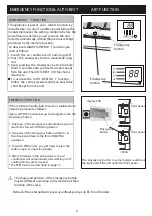


INSTALLA TION MANUAL---Installation of the Indoor unit
INSTALLA TION OF THE INDOOR UNIT
refrigerant
pipe
refrigerant
pipe
insulation
sleeve
connection
(for heat-pump)
cable 1
connection
cable
Probe
cable(for heat-pump)
Condensed water
drain pipe
Covered by vinyl tape
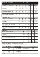
After having connected the pipe according to the instruc-
tions, install the connection cables. Now install the drain
pipe. After connection,lag the pipe, cables and drain pipe
with the insulating material.
1. Arrange the pipes ,cables and drain hose well.
2. Lag the pipe joints with insulating material , securing
it with vinyl tape.
3. Run the bound pipe , Cables and drain pipe through
the wall hole and mount the indoor unit onto the upper
part of the mounting plate securely.
4. Press and push the lower part of the indoor unit tightly
against the mounting plate
mounting plate
INSTALLA TION MANUAL---Installation of the outdoor unit
The outdoor unit should be installed on a solid wall
and fastened securely.
The following procedure must be observed before co-
nnecting the pipes and connecting cables : decide
which is the best position on the wall and leave enough
space to be able to carry out maintenance easily.
Fasten the support to the wall using screw anchors
which are particularly suited to the type of wall;
Use a larger quantity of screw anchors than normally
required for the weight they have to bear to aviod
vibration during operation and remain fastened in the
same position for years without the screws becoming
loose.
The unit must be installed following the national
regulations.
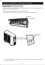
drain pipe
The condensed water and the ice formed in the outdoor
unit during heating operation can be drained away thro-
ugh the drain pipe
1. Fasten the drain port in the 25mm hole placed in the
part of the unit as shown in the picture.
2. Connect the drain port and the drain pipe.
Pay attention that water is drained in a suitable place.
20
Outdoor unit condensed water drainage
(only for heat pump models)
drain port


