SRF Series Splitters and Combiners
Page-6
Revision 0.3
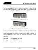
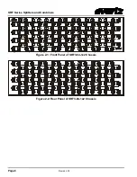
Figure 2-1: Front Panel of SRF3-64-1x2 Chassis
Figure 2-2: Rear Panel of SRF3-64-1x2 Chassis
Страница 1: ...ht 2009 2012 EVERTZ MICROSYSTEMS LTD 5288 John Lucas Drive Burlington Ontario L7L 5Z9 Phone 905 335 3700 Fax 905 335 3573 Internet Sales sales evertz com Tech Support service evertz com Web Page http www evertz com Version 0 3 January 2012 ...
Страница 2: ...IGITAL DEVICE OR PERIPHERAL This equipment has been tested and found to comply with the limits for a Class A digital device pursuant to Part 15 of the FCC Rules These limits are designed to provide reasonable protection against harmful interference when the equipment is operated in a commercial environment This equipment generates uses and can radiate radio frequency energy and if not installed an...
Страница 3: ...er 4x1 Combiner 2 Figure 1 5 1x8 Splitter 8x1 Combiner 3 Figure 1 6 1x16 Splitter 16x1 Combiner 3 Figure 1 7 128x128 L Band Matrix Using XRF6 64x64 Routers and SRF3 64 1x2 Modules 4 Figure 2 1 Front Panel of SRF3 64 1x2 Chassis 6 Figure 2 2 Rear Panel of SRF3 64 1x2 Chassis 6 Figure 2 3 Front Panel of SRF3 32 1x4 Chassis 7 Figure 2 4 Rear Panel of SRF3 32 1x4 Chassis 7 Figure 2 5 Front Panel of SR...
Страница 4: ...ies of future performance either expressed or implied The only warranty offered by Evertz in relation to this product is the Evertz standard limited warranty stated in the sales contract or order confirmation form Although every attempt has been made to accurately describe the features installation and operation of this product in this manual no warranty is granted nor liability assumed in relatio...
Страница 5: ...Figure 1 2 Rear View of SRF3 64 1x2 Chassis The SRF products feature RF coax connectors on both sides of the chassis for mounting on either the front or back of the rack for ease of installation and troubleshooting They also feature an input monitoring port for troubleshooting and diagnostics in the RF plant The SRF1 series is housed in a 1RU frame and the SRF3 series are housed in a 3RU frame RF ...
Страница 6: ... 32 channel 1x4 splitter 4x1 combiner SRF3 16 1x8 16 channel 1x8 splitter 8x1 combiner SRF3 8 1x16 8 channel 1x16 splitter 16x1 combiner 1 1 BLOCK DIAGRAMS COMMON PORTA PORTB MONITOR 20dB passive tap Figure 1 3 1x2 Splitter 2x1 Combiner COMMON PORTA PORTB 20dB passive tap PORTC PORTD MONITOR Figure 1 4 1x4 Splitter 4x1 Combiner ...
Страница 7: ... passive tap PORT C PORT D MONITOR PORT E PORT F PORT G PORT H Figure 1 5 1x8 Splitter 8x1 Combiner COMMON PORT A PORT B 20dB passive tap PORT C PORT D MONITOR PORT E PORT F PORT G PORT H PORT I PORT J PORT K PORT L PORT M PORT N PORT O PORT P Figure 1 6 1x16 Splitter 16x1 Combiner ...
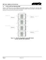
Страница 8: ...se of four SRF3 64 1x2 modules to achieve a 128x128 router using four XRF6 L band routers On the input side the SRF functions as a splitter and as a combiner on the output side allowing non blocking routing of any input to all outputs Figure 1 7 128x128 L Band Matrix Using XRF6 64x64 Routers and SRF3 64 1x2 Modules ...
Страница 9: ...l Output connectors are located on the rear side of the chassis The monitoring port can be used for diagnostics and monitoring This port is a 20dB tap of the common port Terminate this port with a 75 Ohm load when not connected Please note all unused ports on a channel including monitoring ports must be terminated with a 75 Ohm load if they are not connected Please contact Evertz Microsystems for ...
Страница 10: ...SRF Series Splitters and Combiners Page 6 Revision 0 3 Figure 2 1 Front Panel of SRF3 64 1x2 Chassis Figure 2 2 Rear Panel of SRF3 64 1x2 Chassis ...
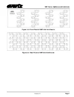
Страница 11: ...SRF Series Splitters and Combiners Revision 0 3 Page 7 Figure 2 3 Front Panel of SRF3 32 1x4 Chassis Figure 2 4 Rear Panel of SRF3 32 1x4 Chassis ...
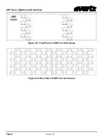
Страница 12: ...SRF Series Splitters and Combiners Page 8 Revision 0 3 Figure 2 5 Front Panel of SRF3 16 1x8 Chassis Figure 2 6 Rear Panel of SRF3 16 1x8 Chassis ...
Страница 13: ...ers Revision 0 3 Page 9 Figure 2 7 Front Panel of SRF3 8 1x16 Chassis Figure 2 8 Rear Panel of SRF3 8 1x16 Chassis SRF1 models occupy 1RU of rack space and have similar layouts but with fewer connectors than the depicted SRF3 models ...
Страница 14: ... 75 Hx9 5D 19 Wx1 75 Hx9 5D 3 2 SRF3 SRF3 SRF3 64 1x2 SRF3 32 1x4 SRF3 16 1x8 SRF3 8 1x16 Number of Channels 64 1x2 s 32 1x4 s 16 1x8 s 8 1x16 s Frequency Range 40MHz 300MHz 40MHz 300MHz 600MHz 2200MHz 800MHz 2200MHz Insertion Loss 4 2dB 0 5dB 7 5dB 0 75dB 11dB 1dB 14dB 1dB Isolation 60dB 55dB 55dB 55dB Return Loss 250MHz 15dB 15dB 14dB 14dB Dimensions 19 Wx5 25 Hx5 5D 19 Wx5 25 Hx5 5D 19 Wx5 25 H...