background image

7700 MultiFrame Manual 

7707VT-8-HS 8 Channel HD/SDI/DVI-ASI Fiber Transmitter 

 Revision 

1.2 

Page - 7 

4. 

STATUS INDICATORS AND DISPLAYS 

The 7707VT-8-HS has 8 LED Status indicators and a 4 digit alphanumeric display on the front card edge 
to show operational status of the card at a glance.  The card edge shaft-encoder/pushbutton is used to 
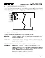
select various displays on the alphanumeric display.  Figure 4-1 shows the locations of the indicators and 
shaft-encoder/pushbutton. 
 

/ MODULE OK

LOCAL FAULT

SERIAL 

RUN/UPGRADE

SERIAL

LED 2

LED 3

LED 4

LED 5

LED 6

LED 7

LED 8

VIDEO 2 STATUS

VIDEO 3 STATUS

VIDEO 4 STATUS

VIDEO 5 STATUS

VIDEO 6 STATUS

VIDEO 7 STATUS

VIDEO 8 STATUS

LED 1

VIDEO 1 STATUS


Figure 4-1: Location of Status Indicators, Jumpers and Controls


4.1. 

STATUS INDICATOR LEDS 

Two large LEDs at the front card-edge display the status of the module as follows: 

 
MODULE OK: 

This Green LED indicates good module health. It will be ON while there is no laser, 
XFP, card-slot or power faults.


LOCAL FAULT: 

This Red LED will illuminate when a fault condition is detected. Possible fault 
conditions include laser, XFP, card-slot or power faults. Whether or not this LOCAL 
FAULT indication is reported to the frame may be determined by the FRAME 
STATUS jumper (see section 5.1).   

 
Eight multi-coloured LEDs indicate the status of the eight corresponding video signals: 
 

VIDEO STATUS:


GREEN

 indicates the presence of a valid input to the corresponding channel. 


YELLOW

 indicates that the corresponding channel has been password-blocked (via 

CTRL/PSWD menu item), or that the input cannot be accommodated in the 
available link bandwidth (see STAT/LINK/USE menu item). 
 

RED

 indicates the detection of video CRC or EDH errors. 


OFF

 indicates a signal loss of signal condition. 

Содержание 7707VT-8-HS

Страница 1: ...TOR LEDS 7 4 2 DOT MATRIX DISPLAY CARD STATUS AND CONTROLS 8 4 2 1 Display of Warning Status Indications 9 4 2 2 Displaying the Video Standard 9 4 2 3 Displaying the Transmit Power 10 4 2 4 Displaying the Nominal Wavelength 10 4 2 5 Displaying the Link Distance Option 10 4 2 6 Displaying the Link Capacity Usage 11 4 2 7 Displaying the Firmware Version 11 4 2 8 Controlling Monitoring Video Output 1...

Страница 2: ...6 6 3 VISTALINK CONTROLLED PARAMETERS 16 6 4 VISTALINK TRAPS 16 Figures Figure 1 1 7707VT 8 HS Block Diagram 1 Figure 2 1 7707VT 8 HS Rear Panel 2 Figure 2 2 Reproduction of Laser Certification and Identification Label 3 Figure 4 1 Location of Status Indicators Jumpers and Controls 7 Figure 4 2 Card Edge Menu Structure 8 Tables Table 6 1 VistaLINK Monitored Parameters 16 Table 6 2 VistaLINK Contro...

Страница 3: ...future performance either expressed or implied The only warranty offered by Evertz in relation to this product is the Evertz standard limited warranty stated in the sales contract or order confirmation form Although every attempt has been made to accurately describe the features installation and operation of this product in this manual no warranty is granted nor liability assumed in relation to an...

Страница 4: ...MultiFrame Manual 7707VT 8 HS 8 Channel HD SDI DVI ASI Fiber Transmitter Revision 1 2 WARNING Never look directly into an optical fiber Non reversible damage to the eye can occur in a matter of milliseconds ...

Страница 5: ...e horizontal or vertical ancillary data space Comprehensive signal and card status monitoring via four digit card edge display or remotely through SNMP and VistaLINK Monitoring output of any input Main module fully hot swappable from front of frame VistaLINK capability is available when modules are used with the 3RU 7700FR C or 350FR frame and a 7700FC VistaLINK Frame Controller module in slot 1 o...

Страница 6: ...SDI SDI SDTi or DVB ASI compatible with HD SDI SMPTE 292M SD SDI SMPTE 259M C SDTi SMPTE 305 2M or EN500083 9 DVB ASI standards These inputs provide adaptive compensation for up to 100m of industry standard Belden 1694A cable at 1 485Gb s or 250m of 1694A cable at 270Mb s SDI INPUT MON OUT One BNC input output connection configurable as an auto sensing SDI SDTi or DVB ASI input or as a loopback mo...

Страница 7: ... 1 LASER PRODUCT 2 1 2 Assembly Assembly or repair of the laser sub module is done only at Evertz facility and performed only by qualified Evertz technical personnel 2 1 3 Labeling Certification and Identification labels are combined into one label As there is not enough room on the product to place the label it is reproduced here in the manuals There is no date of manufacture on this label as it ...

Страница 8: ...e making a connection The transmission characteristics of the fiber are dependent on the shape of the optical core and therefore care must be taken to prevent fiber damage due to heavy objects or abrupt fiber bending Evertz recommends that you maintain a minimum bending radius of 5 cm to avoid fiber bending loss that will decrease the maximum attainable distance of the fiber cable For further info...

Страница 9: ...uts 1 Output configurable as input or output Standards SMPTE 292M SMPTE 259 C SMPTE 305 2M SDTi EN500083 9 DVB ASI Connector BNC per IEC 61169 8 Annex A Signal Level 800mV nominal DC Offset 0V 0 5V Rise and Fall Time 900ps nominal 270Mb s 270ps 1 485Gb s Overshoot 10 of amplitude Return Loss 12dB to 1 5Gb s Alignment Jitter 0 2UI 3 3 OPTICAL OUTPUT Number of Outputs 1 Connector Female LC Duplex Re...

Страница 10: ...UL 60065 03 IEC 60065 2001 12 7th Edition Complies with CE Low voltage directive 93 68 EEC Laser Safety Complies with 24 CFR 1040 10 and 1040 11 except for deviations pursuant to LN No 50 dated July 26 2001 Complies with IEC 60825 1 Am 2 EMI RFI Complies with FCC regulations for class A devices Complies with EU EMC directive 89 336 EEC 3 6 PHYSICAL Number of slots 2 ...

Страница 11: ...R LEDS Two large LEDs at the front card edge display the status of the module as follows MODULE OK This Green LED indicates good module health It will be ON while there is no laser XFP card slot or power faults LOCAL FAULT This Red LED will illuminate when a fault condition is detected Possible fault conditions include laser XFP card slot or power faults Whether or not this LOCAL FAULT indication ...

Страница 12: ...ault LINK Optical Link Output Selections VID1 Video 1 VID7 Video 7 USED Used for Transport PSWD Password Protect 0 9999 Enter Password Factory Default 7154 Selections Selections VID1 Video 1 VID8 Video 8 NEW New Password 0 9999 Enter Password Selections ON Enable Channel OFF Block Channel Selections PSWD Password Blocked OFF Monitor Off SLOT ERR Slot Error Supersedes XFP ERR XFP Error Supersedes L...

Страница 13: ...nputs To display the video standard select the STAT menu item in menu level 1 then use the shaft encoder to display the desired video channel from VID1 to VID8 and press the shaft encoder to select it For the sake of brevity only the description for video input 1 will be provided The settings for Video Inputs 2 to 7 VID2 to VID7 and Video Input Output 8 VID8 are the same STAT VID1 Standards LOS IO...

Страница 14: ...velength from the XFP module in nm To display the nominal wavelength select the STAT menu item in level 1 use the shaft encoder to display the desired selection WL and press the shaft encoder to select and display it STAT LINK WL 0 to 3276 75nm NA The following indications are available 0 to 3276 75nm Optical output wavelength NA Unavailable pluggable XFP module not detected 4 2 5 Displaying the L...

Страница 15: ...s an example of the firmware version For example VER 1 0 BLD 067 4 2 8 Controlling Monitoring Video Output The MON menu item allows the user to control which input video signal VID 1 through VID7 will be passed through to the Input channel 8 output on the 7707VT 8 HS To select the output signal select the CTRL menu item in menu level 1 use the toggle switch to display the MON option and press the ...

Страница 16: ...ications are available ON Enables the selected video channel OFF Blocks the selected video channel The user can set a new password by selecting the NEW option from the menu CTRL PSWD Enter Password NEW 0 9999 Enter Password Selecting NEW rather than a channel will allow the user to define a password 0 9999 4 2 10 Setting the Orientation of the Text on the Card Edge Display The display option allow...

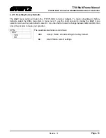
Страница 17: ...rn all settings to factory defaults select the CTRL menu item in menu level 1 use the shaft encoder to display the FRST menu selection and use the pushbutton to select it Use the shaft encoder to change between YES and NO then press the encoder to make your selection CTRL FRST YES NO The possible selections are as follows YES Accept Return all card settings to factory default NO Abort Retain curre...

Страница 18: ...y the power supply LEDs or the frame s Fault Tally output but will only be indicated by the local fault indicator on the card itself 5 2 CONFIGURING THE MODULE FOR FIRMWARE UPGRADES UPGRADE The UPGRADE jumper is used when firmware upgrades are being done to the card For normal operation this jumper should be installed in the RUN position See the Upgrading Firmware section of this manual for more i...

Страница 19: ...ck that the configuration has been carried out There are 3 components of SNMP 1 An SNMP manager also known as a Network Management System NMS is a computer running special software that communicates with the devices in the network Evertz VL Fiber demo Manager graphical user interface GUI third party or custom manager software may be used to monitor and control Evertz VistaLINK enabled fiber optic ...

Страница 20: ...ONTROLLED PARAMETERS The following parameters can be remotely controlled through the VistaLINK interface Parameter Description Controls VID8 Monitor Output Controls VID8 Monitor Output Channel Protection Enable or Disable Channel Password Protection Channel Protection Password Sets the channel protection password Table 6 2 VistaLINK Controlled Parameters 6 4 VISTALINK TRAPS The following traps can...

Отзывы: